
Drive device for an element to be driven

a technology of a drive device and an element, which is applied in the direction of multi-purpose tools, door/window fittings, construction, etc., can solve the problems of frequent problems, insufficient toothed belt drivers, and requiring costly repairs

Active Publication Date: 2022-09-20
GEBR BODE & CO GMBH
View PDF31 Cites 0 Cited by
  • Summary
  • Abstract
  • Description
  • Claims
  • Application Information

AI Technical Summary

Benefits of technology

The present invention provides an improved drive device with a toothed belt for driving an element. The drive device should improve energy utilization and ensure low-maintenance operation of the toothed belt drive. Additionally, the drive device should have a compact design and be space-saving. When multiple force drivers are simultaneously located in force driver recesses of the toothed disc, the load on the toothed belt is significantly reduced because the forces are distributed over the multiple force drivers. Furthermore, it is beneficial to only drive the toothed discs that do not contact the force drivers during the normal operation to reduce slipping of the force drivers on the toothed disc. In a particularly advantageous variation, the force drivers are exclusively fastened on the toothed belt by means of clamping, which maintains the structure of the toothed belt and keeps the cables or wires in the interior of the toothed belt intact.

Problems solved by technology

Problems frequently arise due to the fact that the mounting of the drivers on the toothed belt does not suffice for transmitting high driving forces.
The drivers separate due to load peaks or in the course of their operation and therefore necessitate costly repairs.
The cables or wires, which are crucial for absorbing the tensile forces, cannot be damaged when the drivers are attached because the stability and tearing resistance of the toothed belt would otherwise be impaired.
This also limits the force transmission to elements to be driven by means of drivers.
Another problem can be seen in that a force transmission only takes place along the longitudinal extent of the toothed belt, i.e. in the x-direction.
Although a deflection of the element driven by means of drivers would be possible, e.g. with the aid of guide rails, this is associated with a significant loss of driving energy due to the division of the force application into an x-component (parallel to the moving direction of the toothed belt) and a y-component (transverse to the moving direction of the toothed belt).
This problem arises, e.g., in swinging-sliding doors, which are displaced parallel and sectionally oblique to the outer vehicle wall and guided in a curved guideway.
This division causes considerable losses of driving energy.
Known drive systems frequently require excessive structural space and also have a relatively elaborate construction.

Method used


Image

  • Drive device for an element to be driven
  • Drive device for an element to be driven
  • Drive device for an element to be driven

Examples


Embodiment Construction

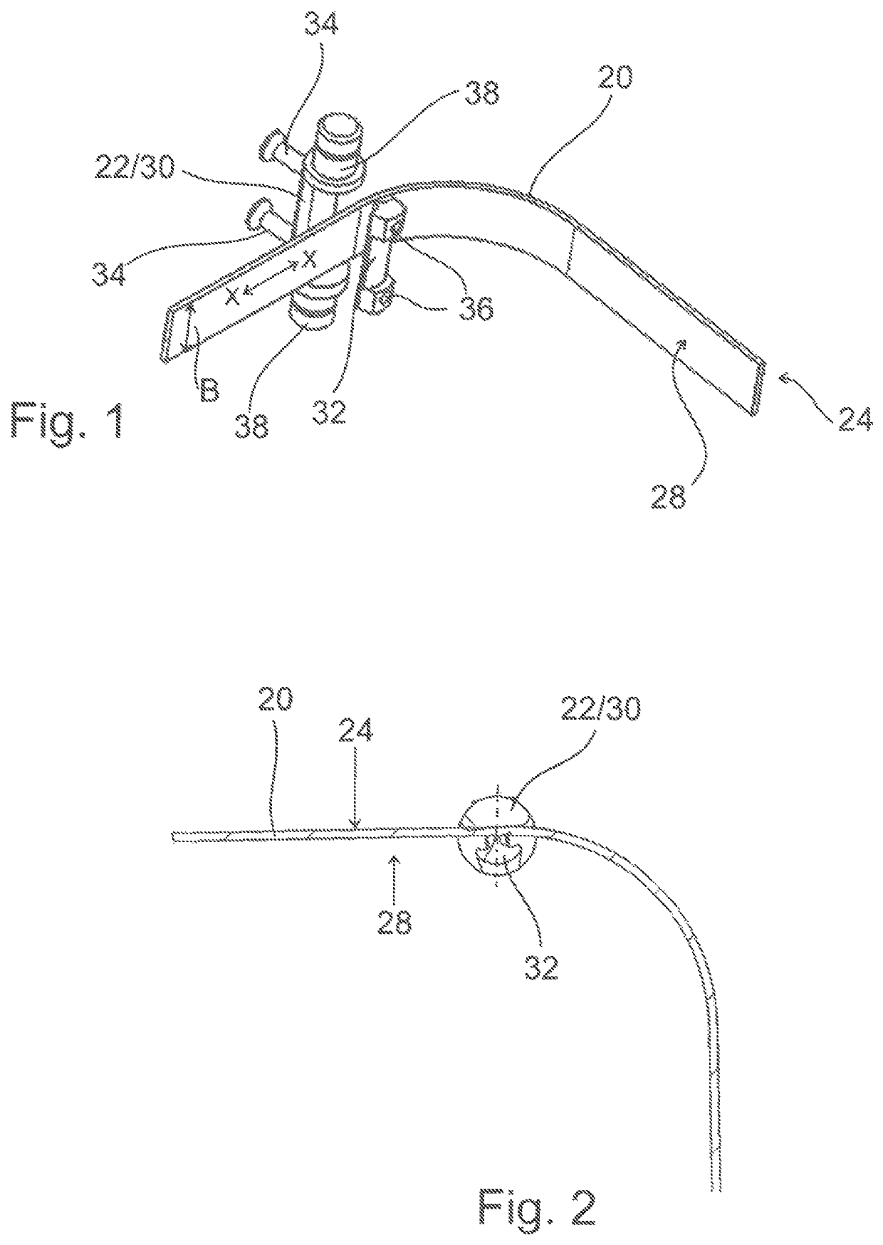
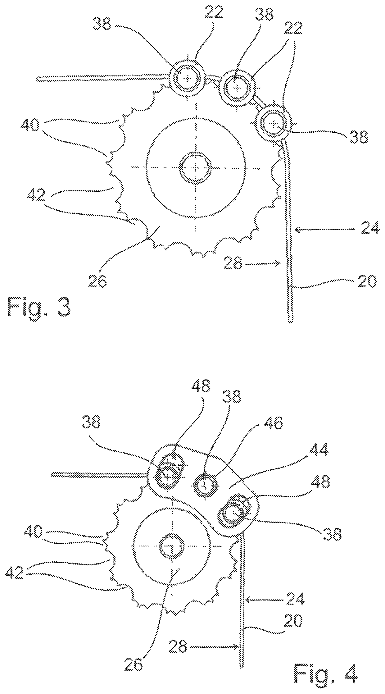
[0053]FIG. 1 shows a section of a toothed belt 20, on which an inventive force driver 22 is fastened. The toothed belt has an outer side 24 and an inner side 28 that faces a toothed disc 26 (see FIGS. 3 and 4). The inner side 28 usually has teeth 28 that are not illustrated in the figures.

[0054]The force driver 22 is formed by an essentially cylindrical body that is divided into an upper part 30 and a lower part 32. In the exemplary embodiment shown, the upper part 30 and the lower part 32 are connected to one another with connecting means 34, preferably clamping screws, in such a way that the toothed belt 20 is arranged between these two parts. In this case, the lower part 32 is arranged on the inner side 28 and the upper part 30 is arranged on the outer side 24 of the toothed belt. A serrated inner surface of the lower part 32, which faces and corresponds to the teeth of the toothed belt 20, is not illustrated in this figure. The teeth engage into correspondingly shaped depression...


PUM


Abstract

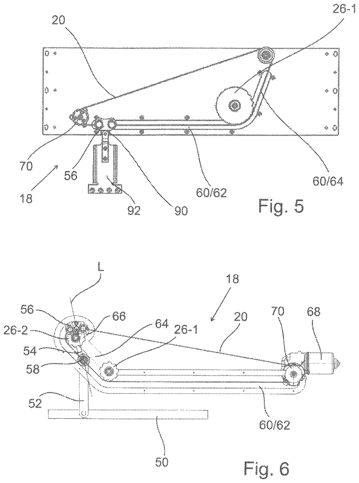
The invention relates to a drive device for driving an element, having the following: a toothed belt drive with a toothed belt, a frame element which forms two opposite connection plates and a connection wall that connects the two connection plates together, at least three elongated force driving elements which are secured to the toothed belt and are aligned parallel to the width (B) of the toothed belt and parallel to one another and which are arranged within the frame element, wherein a central force driving element is rotationally fixed to the two connection plates, and the end sections of each adjacent outer force driving element extend through curved elongated holes of the connection plate, whereby the outer force driving element can be pivoted and the end faces of the outer force driving elements have cylindrical projections, which are designed as axle stubs and each of which has a roller, outside of one of the connection plates, a toothed disc with tooth recesses for catching teeth of the toothed belt and force driving element recesses for catching the force driving elements, a non-linear guide path, at least some sections of which run parallel to the extension of the toothed belt and in which the rollers arranged on the outer force driving elements are guided, and a drive means which is connected to the frame element and is used to connect to the element to be driven.

Description

RELATED APPLICATIONS[0001]This application is a National Phase of PCT Patent Application No. PCT / EP2016 / 077457 having International filing date of Nov. 11, 2016. The contents of the above application is incorporated by reference as if fully set forth herein in its entirety.FIELD AND BACKGROUND OF THE INVENTION[0002]The present invention pertains to a drive device for driving an element with a toothed belt, a toothed disc and an at least sectionally nonlinear guideway, in which the element is guided with the aid of guide means.[0003]Most toothed belts have a smooth side and a side with teeth. The smooth side is usually located outside whereas the inner side of the toothed belt is provided with teeth. The toothed belt is wrapped around a toothed disc, wherein the teeth of the toothed belt engage into the recesses of the toothed disc such that the toothed disc drives the toothed belt by means of the tooth recesses and the teeth.[0004]Toothed belt drives are frequently used for the tran...

Claims


Application Information

Patent Timeline
IPC IPC(8): E05D15/10E05F15/646E05F15/655E05F15/681
CPCE05D15/1047E05F15/646E05F15/655E05F15/681E05D2015/1026E05D2015/1057E05Y2900/531Y10T16/56E05Y2900/506E05Y2900/51E05D2015/1055
Inventor LINNENKOHL, LARS
Owner GEBR BODE & CO GMBH
Learn More