
Current protection circuit and method for high voltage system

a current protection circuit and high voltage technology, applied in emergency protective circuit arrangements, emergency protective arrangements for limiting excess voltage/current, instruments, etc., can solve problems such as unsafe system failure and component damag

Active Publication Date: 2022-08-16
UBTECH ROBOTICS CORP LTD
View PDF6 Cites 2 Cited by
  • Summary
  • Abstract
  • Description
  • Claims
  • Application Information

AI Technical Summary

Benefits of technology

This solution provides wider protection scope and improved reliability for high-voltage systems, preventing component damage and ensuring system stability by monitoring and controlling current on the high voltage side, thus enhancing cost-effectiveness and reliability compared to conventional low-voltage side protection methods.

Problems solved by technology

One problem with the current protection solution is that the current does not flow through the detection component on the low voltage side when the load failure occurs.
As a result, the high voltage system cannot be protected, which may result in component damage or unsafe system failure.

Method used


Image

  • Current protection circuit and method for high voltage system
  • Current protection circuit and method for high voltage system

Examples


Embodiment Construction

[0008]The disclosure is illustrated by way of example and not by way of limitation in the figures of the accompanying drawings, in which like reference numerals indicate similar elements. It should be noted that references to “an” or “one” embodiment in this disclosure are not necessarily to the same embodiment, and such references can mean “at least one” embodiment.

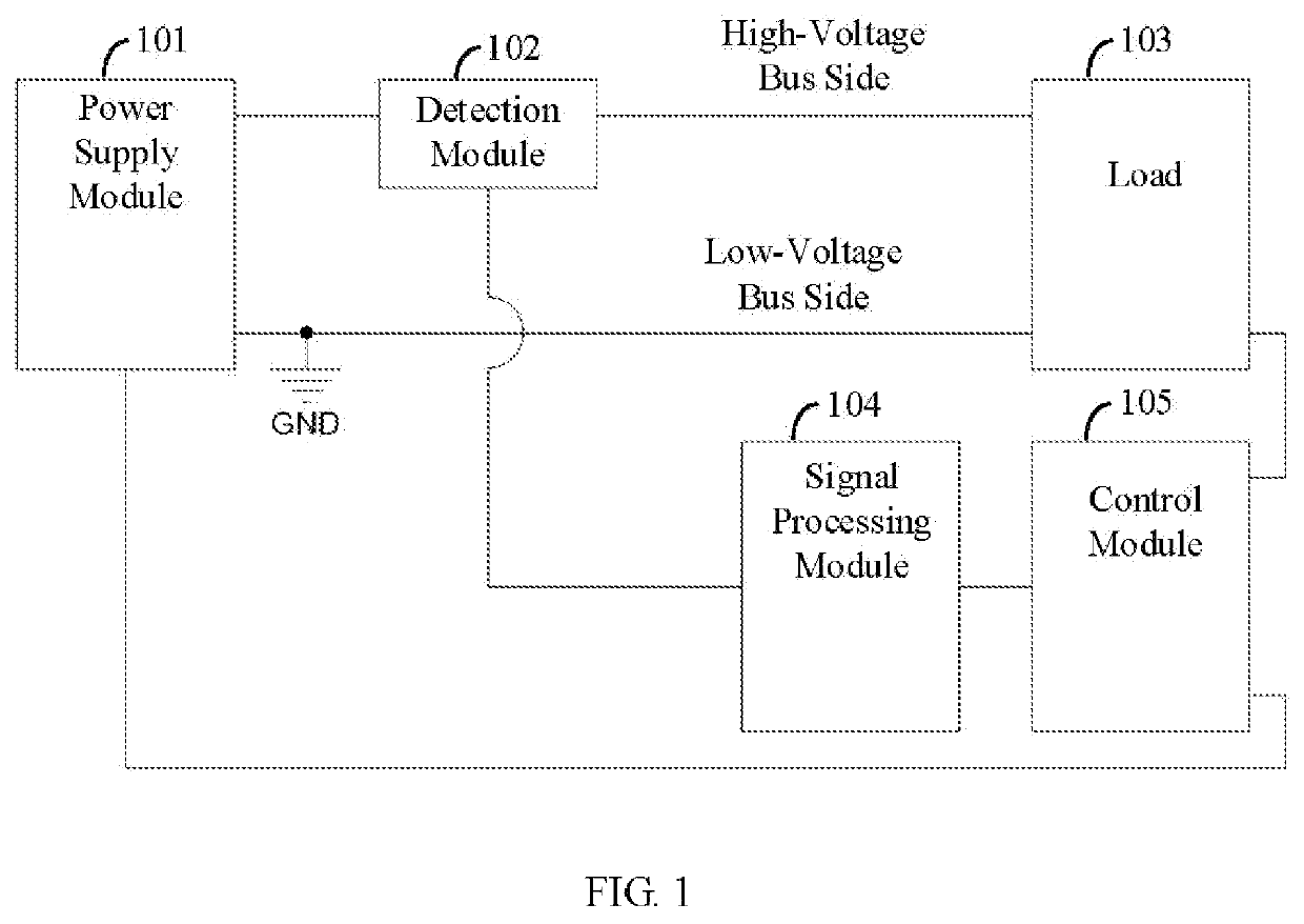
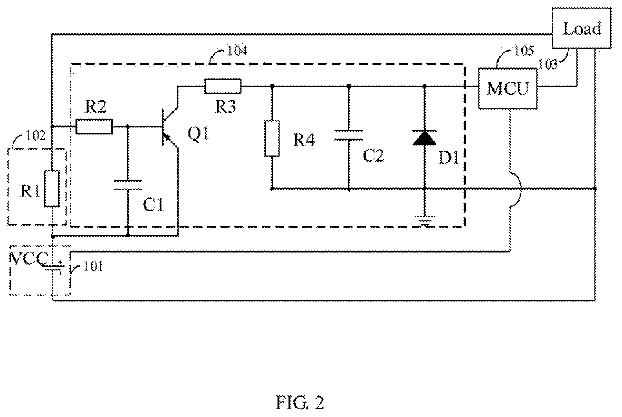
[0009]A generalized description of the current protection circuit and method for a high voltage system is provided. The current flowing through the bus on the high voltage side of the high voltage system is monitored in real-time. When the value of the amplified current is greater than a preset threshold, the control module receives a determined digital level signal, which can be used to control the high voltage system, thereby controlling the power supply module or the load to achieve current protection for the bus. Moreover, it is beneficial to cost control for the current protection for bus on the high-voltage side of...


PUM


Abstract

A current protection circuit for a high voltage system includes: a power supply module to supply power to a load through a high voltage bus and a low voltage bus; a detection module connected to the high voltage bus and used to detect a value of current flowing through the high voltage bus; a signal processing module electrically connected to the detection module and used to amplify the current flowing through the high voltage bus; and a control module electrically connected to the signal processing module, the power supply module, and the load, and used to disconnect the load from the power supply module or perform current limiting for the load when the value of the amplified current exceeds a preset threshold.

Description

CROSS REFERENCE TO RELATED APPLICATIONS[0001]This application claims priority to Chinese Patent Application No. 201811554442.5, filed Dec. 18, 2018, which is hereby incorporated by reference herein as if set forth in its entirety.BACKGROUND1. Technical Field[0002]The present disclosure generally relates to over-current protection circuits, and particularly to a current protection circuit and method for a high voltage system.2. Description of Related Art[0003]Many high-voltage systems, such as high-power servo systems, frequency converters, air conditioners, CNC machines, include a power supply system, a current detection system, a control system, and a load system. In order to improve the reliability of the high voltage systems, it is necessary to monitor the current flowing through the buses of the high voltage systems in real time, so as to realize the overcurrent protection. That is, when the value of the current is greater than or equal to a threshold, control is performed to im...

Claims


Application Information

Patent Timeline
Patent Type & Authority Patents(United States)
IPC IPC(8): H02H9/02G01R33/07G01R33/00
CPCH02H9/02G01R33/0094G01R33/07G01R33/072G01R19/16547
Inventor XIONG, YOUJUNZHOU, SHENGWANG, MALINFAN, WENHUAPANG, JIANXIN
Owner UBTECH ROBOTICS CORP LTD
Learn More