Backlight module having an optical film and display apparatus having the same
a backlight module and optical film technology, applied in the field of optical module and display apparatus, can solve the problems of reducing the overall assembly yield rate, low haze of prism sheet, and inability to use diffusion sheets with low haze, etc., and achieves good light collecting efficiency and high assembly yield rate
- Summary
- Abstract
- Description
- Claims
- Application Information
AI Technical Summary
Benefits of technology
Problems solved by technology
Method used
Image
Examples
first embodiment
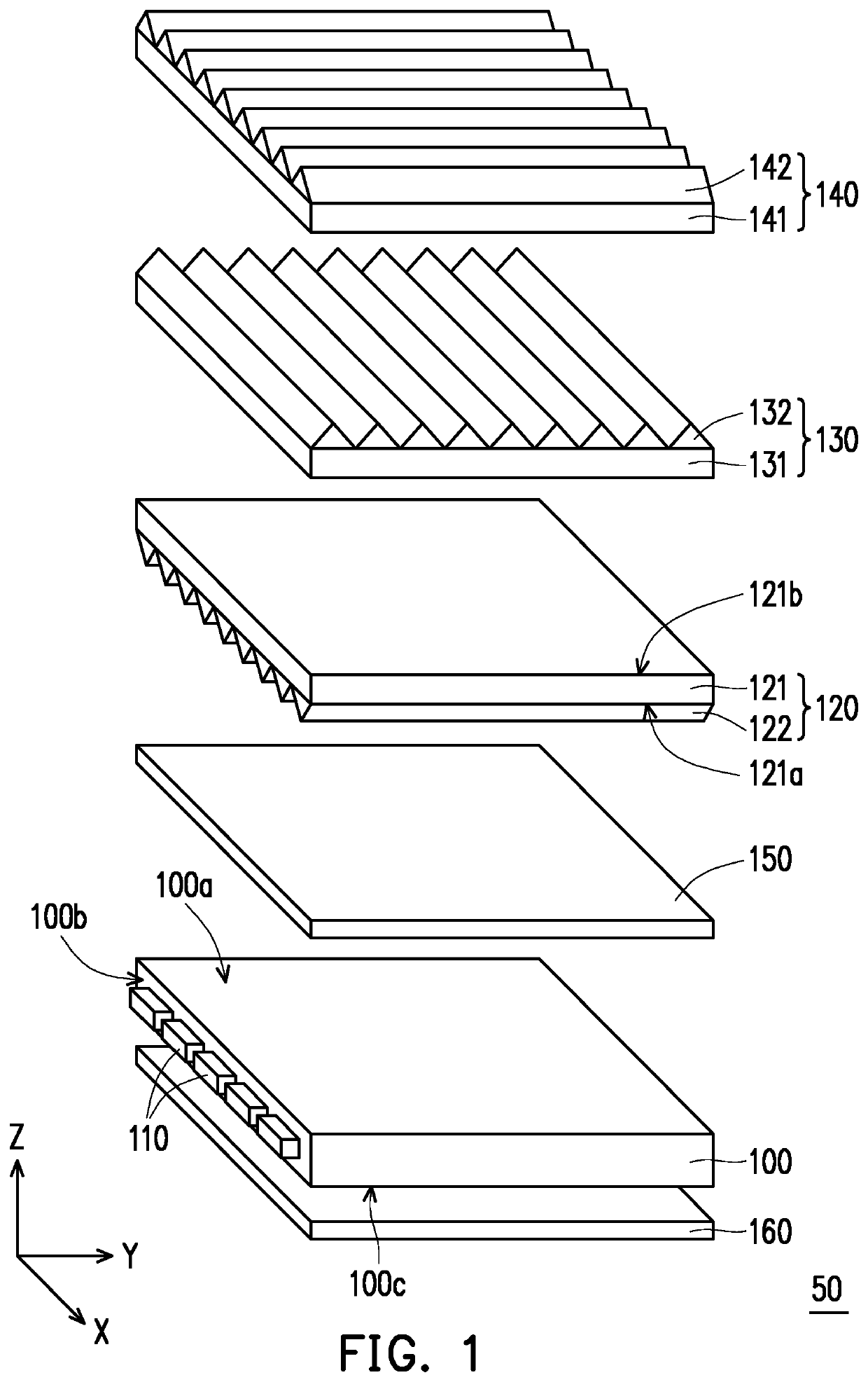
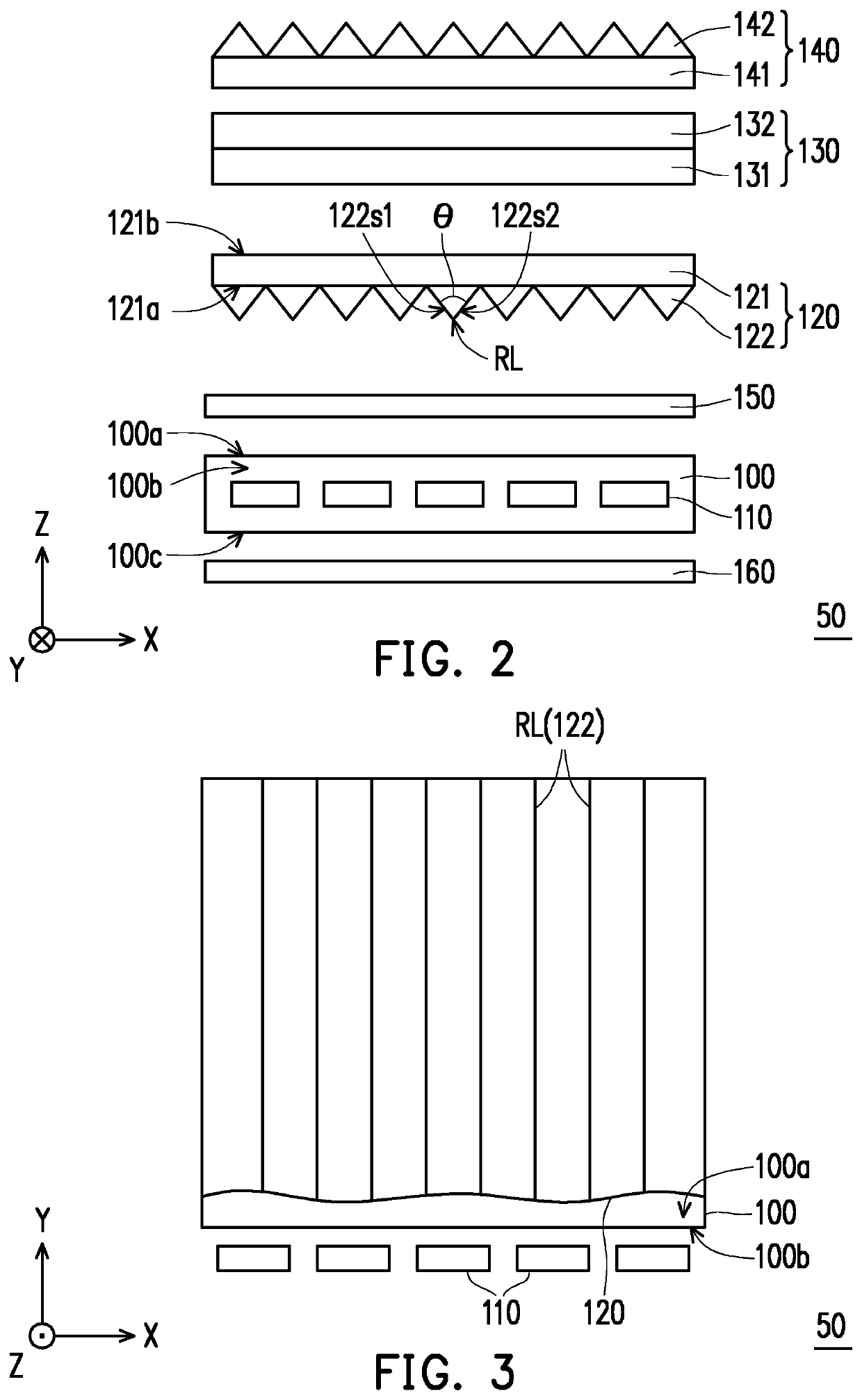
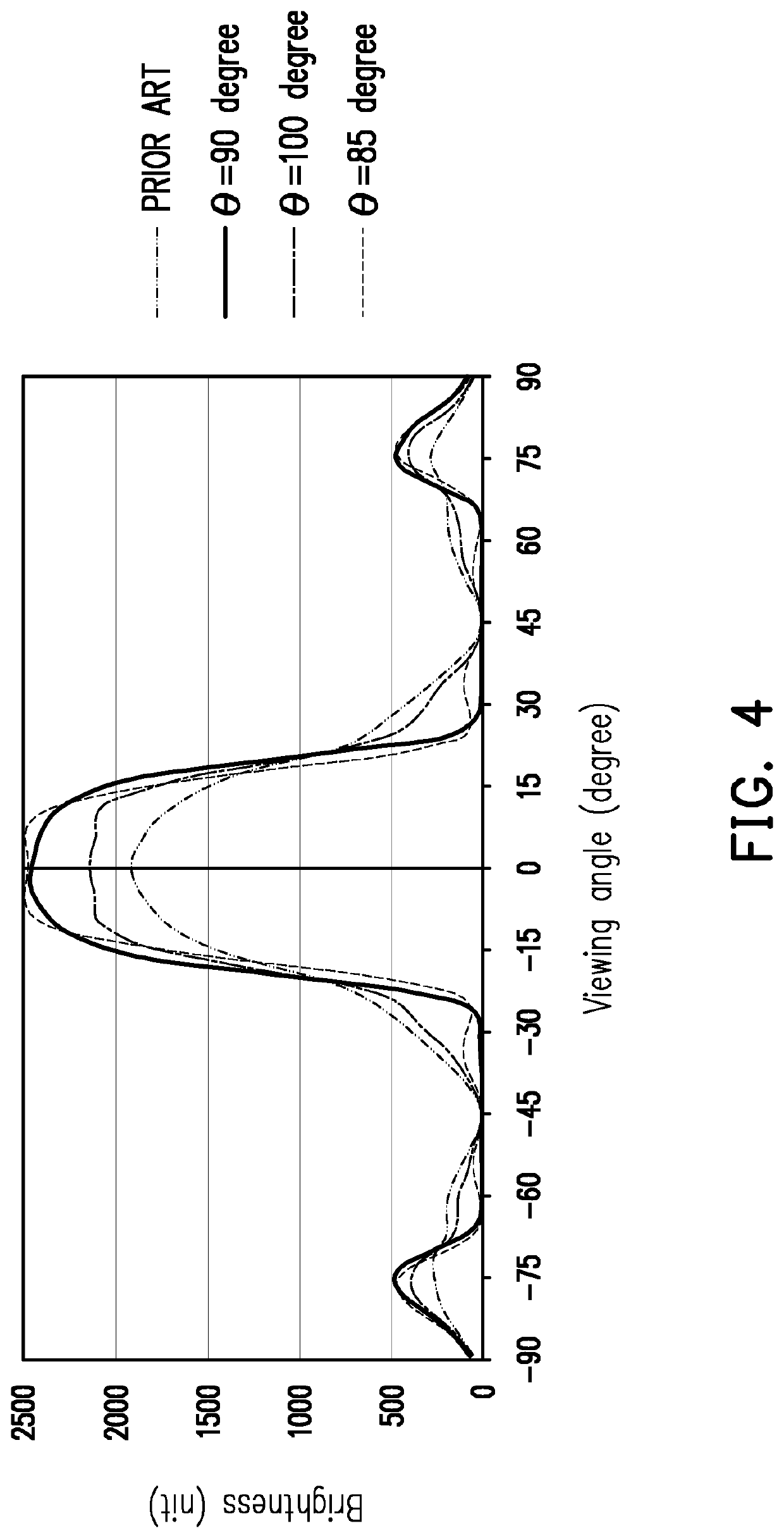
[0032]FIG. 1 is a schematic view of a backlight module according to the disclosure. FIG. 2 is a schematic side view of the backlight module in FIG. 1. FIG. 3 is a schematic top view of the backlight module in FIG. 1. FIG. 4 is a diagram of a curve showing the relation between viewing angle and brightness of the backlight module in FIG. 1. It should be noted here, for clarity, FIG. 3 only shows a light guide plate 100, a light source 110, and optical microstructures 122 of an optical film 120 in FIG. 1.
[0033]Referring to FIG. 1 and FIG. 2, a backlight module 50 includes the light guide plate 100, the light source 110, and the optical film 120. The light guide plate 100 has a light emitting surface 100a and a light incident surface 100b, and the light emitting surface 100a and the light incident surface 100b are connected to each other. The optical film 120 is overlapped with the light emitting surface 100a of the light guide plate 100. The light source 110 is disposed on a side of th...
fourth embodiment
[0056]FIG. 12 is a schematic view of a backlight module according to the disclosure. FIG. 13 is a schematic top view of the backlight module in FIG. 12. It should be noted here, for clarity, FIG. 13 only show the light guide plate 100, the light sources 110, the optical microstructures 122E of the optical film 120E and the prism structures 132E of the first prism sheet 130E. Referring to FIG. 12 and FIG. 13, the different between the backlight module 50C of the embodiment and the backlight module 50 in FIG. 3 is the extending direction of the optical microstructures.
[0057]In the embodiment, the orthogonal projection of the ridge line RL-C (namely, the extending path) of the optical microstructure 122E of the optical film 120E on the light emitting surface 100a of the light guide plate 100 may be parallel to the light incident surface 100b. That is, the angle between the extending direction of the optical microstructure 122E of the optical film 120E and the light incident surface 100...
fifth embodiment
[0060]FIG. 14 is a schematic view of a backlight module according to the disclosure. FIG. 15 is a schematic top view of the backlight module in FIG. 14. It should be noted here, for clarity, FIG. 15 only show the light guide plate 100, the light sources 110, the optical microstructures 122F of the optical film 120F, the prism structures 132F of the first prism sheet 130F and the prism structures 142F of the second prism sheet 140F. Referring to FIG. 14 and FIG. 15, the difference between the backlight module 50D of the embodiment and the backlight module 50C in FIG. 12 is the extending direction of the optical microstructures.
[0061]In the embodiment, the orthogonal projection of the ridge line RL-D (namely, the extending path) of the optical microstructure 122F of the optical film 120F on the light emitting surface 100a of the light guide plate 100 may not be parallel to and may not be perpendicular to the light incident surface 100b. Specifically, the angle between the extending di...
PUM
| Property | Measurement | Unit |
|---|---|---|
| angle | aaaaa | aaaaa |
| angle | aaaaa | aaaaa |
| apex angle | aaaaa | aaaaa |
Abstract
Description
Claims
Application Information
 - R&D
- Intellectual Property
- Life Sciences
- Materials
- Tech Scout
- Unparalleled Data Quality
- Higher Quality Content
- 60% Fewer Hallucinations
Browse by: Latest US Patents, China's latest patents, Technical Efficacy Thesaurus, Application Domain, Technology Topic, Popular Technical Reports.
© 2025 PatSnap. All rights reserved.Legal|Privacy policy|Modern Slavery Act Transparency Statement|Sitemap|About US| Contact US: help@patsnap.com


