
Medical scope accessory, medical scopes comprising the accessory, and use thereof

a technology of medical scopes and accessories, applied in the field of medical scope accessories and medical scopes comprising accessories, can solve the problems of affecting the ability of the endoscopist to visualise affecting the ability of the endoscopist to see the entire surface of the mucosa, and significant risks of potentially serious complications

Active Publication Date: 2022-08-02
KEYMED MEDICAL & INDAL EQUIP
View PDF19 Cites 0 Cited by
  • Summary
  • Abstract
  • Description
  • Claims
  • Application Information

AI Technical Summary

Benefits of technology

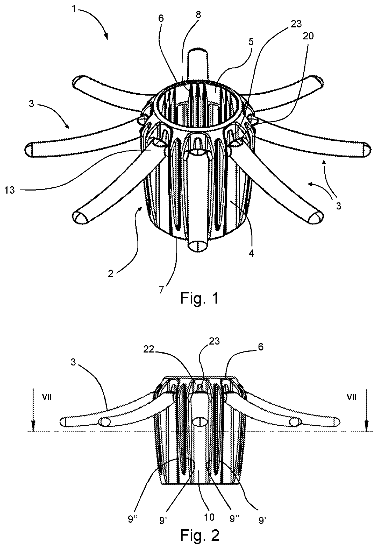
[0010]In use of the cover of the invention the locus of movement of each of the projecting elements is limited by the interaction of the detent with the contact region on the tubular member. On pivoting movement of a projecting element towards the distal direction, the detent will impact on the contact region, thereby hindering further pivoting movement of the base of the projecting element. Movement of the rest of the projecting element may, however, be unaffected by the detent. Thus, for example, in the preferred arrangement in which the projecting elements are flexible, the projecting elements may still be capable of being everted such that their distal tips are directed distally with regard to the scope shaft. Accordingly, the base portion of the projecting element can be movable through an angular range having a first, proximal range in which the base portion is relatively freely pivotable and a second, distal range in which, following initial impact of the detent on the contact region, the continued distal movement of the base portion by pivoting is resisted or even stopped. The greater resistance to movement towards the distal direction may be advantageous in terms of controlling the position and movement of the projecting elements in use, for example enabling increased opening force to be applied to folds of the cavity wall for opening folds and / or giving increased resistance to withdrawal of the scope which can enable more effective examination. In the second, distal angular range, even if further pivoting at the mountings is reduced or prevented, in the case of flexible projecting elements, further distal bending of the remainder of the projecting element may still be achievable through bending of the projecting element at an intermediate position displaced from the base, rather than primarily by bending at the base of the projecting element. That can advantageously reduce any tendency of the projecting elements, during retraction of the scope, to come into contact with the distal edge of the cover. It may also reduce the tendency for the projecting elements to contact, or to bend across immediately in front of, the distal surface. The positioning of the projecting elements is thus better controllable to obtain a desired interaction with the surrounding cavity wall and / or to achieve visualisation of the distal ends of the projecting elements within a desired range of positions relative to the tip of the scope. The present invention thus offers the possibility of improved visualisation by the clinician.
[0036]In an embodiment, at least one of said projecting elements comprises a measurement scale. In a variant of that embodiment two or more projecting elements with measurement scales may be present, or each projecting element may have a measurement scale. In such embodiments the cover of the invention facilitates the assessment of the size of a structure visualised in a body cavity. Structures that may advantageously be measured using the scale include polyps. Because the scale is provided on a movable projecting element it provides a versatile approach to measurement, since the projecting element is readily movable relative to the distal tip of the scoping device. That enables the distal tip and a projecting element carrying a said scale to be manoeuvred into suitable positions relative to one another and to a structure to be assessed to enable a relatively accurate measurement to be made using the measuring scale on the projecting element. Importantly, in addition to their advantageous manoeuvrability to permit visualisation of a said measurement scale, the projecting elements of the device of the invention can serve to open up areas of tissue when the projecting elements become everted during withdrawal of the scope, allowing improved visualisation of structures that may otherwise be hidden within the folds of tissue. Thus, the combination of effective opening up the folds of tissue together with relative movability of the measurement scale and the lens of the distal tip provide a simple approach to polyp assessment that may be used on a standard scoping apparatus, providing versatility in the direction of measurement as well as reliable measurement. Furthermore, there is no need for advancing of an additional part from the scoping device for effecting measurement—the operator only needs to advance a snare or other cutting device from the scoping device if it is concluded that a polyp is to be removed.

Problems solved by technology

Whilst colonoscopic and enteroscopic examinations are the most effective techniques to assess the state of health of the bowel, they are inconvenient, uncomfortable, expensive procedures that are associated with significant risks of potentially serious complications.
In all endoscopic examinations, folds present may hamper the endoscopist's ability to visualise the entire surface of the mucosa and in particular, detect pre-malignant and malignant lesions tucked away on the proximal face of these folds during extubation.
However, in practice, the rings or partial rings can collapse only to a relatively limited extent.
The remaining relatively large overall diameter of the sleeve including the collapsed rings is undesirable.

Method used


Image

  • Medical scope accessory, medical scopes comprising the accessory, and use thereof
  • Medical scope accessory, medical scopes comprising the accessory, and use thereof
  • Medical scope accessory, medical scopes comprising the accessory, and use thereof

Examples


first embodiment

[0041]FIG. 1 is a perspective view of cover according to the invention for use in sigmoidoscopy.

[0042]FIG. 2 is a side view of the cover of FIG. 1;

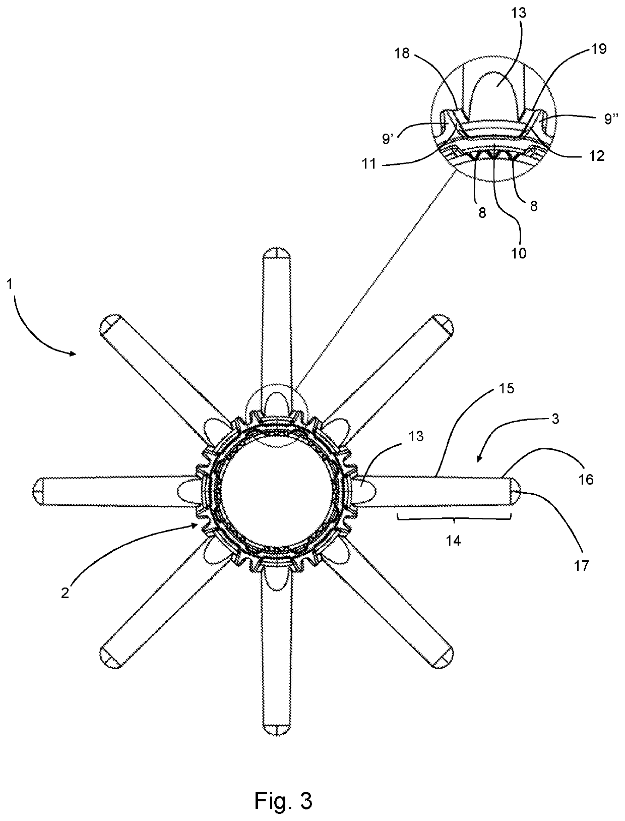
[0043]FIG. 3 is a bottom view of the cover of FIG. 1 and includes a detail view showing a portion of the base of a projecting element and the adjacent portion of the tube;

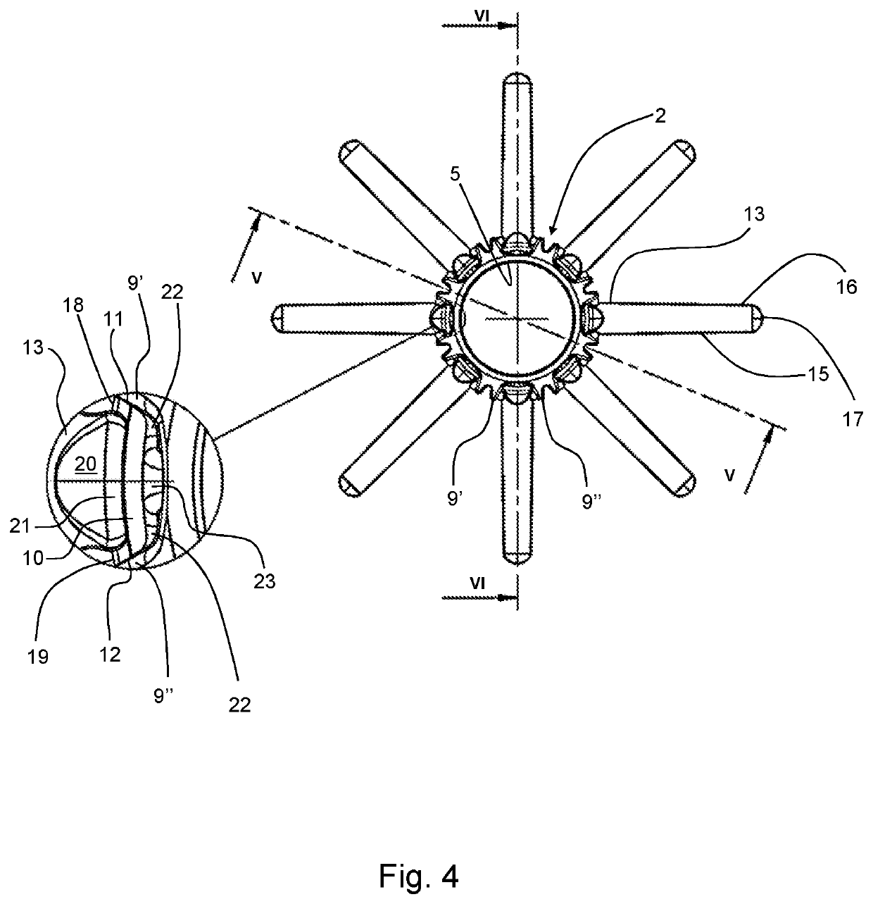
[0044]FIG. 4 is a view of the cover of FIG. 1 from above, showing a detail of a portion of the cover at the base portion of a projection element;

[0045]FIG. 5 is a vertical section through the cover of FIGS. 1 to 4 along the line V-V shown in FIG. 4;

[0046]FIG. 6 is a vertical section through the cover of FIGS. 1 to 4 along the line VI-VI shown in FIG. 4, further showing in section a detail of a portion of the cover showing the base portion of the projecting element and the adjacent portion of the tube in section;

[0047]FIG. 7 is a horizontal section along the line VII-VII of FIG. 2;

second embodiment

[0048]FIG. 8 is a perspective view of cover according to the invention for use in enteroscopy;

[0049]FIG. 9 is a bottom view of the cover of FIG. 8 and includes a detail view showing a portion of the base of a projecting element and the adjacent portion of the tube;

[0050]FIG. 10 is a view of the cover of FIG. 1 from above, showing a detail of a portion of the cover at the base portion of a projection element;

[0051]FIG. 11 is a section through a cover according to FIGS. 1 to 7 in the rest position;

[0052]FIG. 12 is a section through the cover of FIG. 11 showing the projecting elements in a forward position;

[0053]FIG. 13 is a schematic view of a cover according to the invention as used in a first stage of colonoscopic examination;

[0054]FIG. 14 is a schematic view of the cover of FIG. 13 during a main visualisation stage of a colonoscopic examination;

third embodiment

[0055]FIG. 15 is a perspective view of a projecting element for use in a cover according to the invention;

[0056]FIG. 16 is a partial side view of the cover of the third embodiment of the invention in which the projecting elements are in an extreme distal position; and

[0057]FIG. 17 is a section through the cover shown in FIG. 16 along the line A-A shown in FIG. 16.

[0058]The invention is described hereafter with reference to first and second illustrative embodiments of the invention comprising a tip cover device for sigmoidoscopy (FIGS. 1 to 7) and a tip cover device for enteroscopy (FIGS. 8 to 10). The invention may be applied in cover devices suitable for other types of internal examination, for example endoscopy, colonoscopy, and any other technique in which a visualisation device is advanced into a bodily orifice for examination.

[0059]FIGS. 1 to 7 show, as a first illustrative embodiment of the invention, a scope cover of dimensions suitable for mounting on the end of a sigmoidosc...


PUM


Abstract

A cover (1) for a shaft of a medical scoping device comprises tubular member (2) arranged for application on the distal tip of the medical scoping device. The cover (1) comprises a plurality of projecting elements (3) spaced apart circumferentially around the tubular member (2), each projecting element having a base portion (13) and an arm portion (14). The projecting elements are pivotably mounted on the tubular member about a pivot axis. The base portion (13) comprises a detent (20), and the tubular member comprises a contact region, for example a protuberance (23), said contact region being located such that pivoting movement of the projecting element for moving the arm portion in a distal direction can effect impacting of the detent (20) on the contact region (23).

Description

[0001]This application is a National Stage Application of PCT / GB2017 / 051341, filed May 12, 2017, which claims priority to United Kingdom Patent Application No. 1608380.0, filed May 12, 2016.FIELD OF THE INVENTION[0002]The present invention relates to a device for use with a medical scoping device shaft and to a medical scoping device including a said device.BACKGROUND OF THE INVENTION[0003]In endoscopic examinations / procedures, flexible instruments designed to view the gastrointestinal tract are inserted along a body cavity to an internal part such as the stomach, duodenum, small intestine or large intestine. The instruments are provided with imaging devices, for example fibre-optic or charge-couple device (CCD) cameras, which enable images to be transmitted around bends and images to be produced to a display screen. Accordingly, it is possible to view the inside surfaces of the oesophagus, stomach and duodenum using a gastroscope, the small intestine with an enteroscope, part of th...

Claims


Application Information

Patent Timeline
Patent Type & Authority Patents(United States)
IPC IPC(8): A61B1/32A61B1/00A61B1/31A61B17/00A61B90/00
CPCA61B1/32A61B1/0014A61B1/00087A61B1/00089A61B1/00101A61B1/31A61B2017/00296A61B2090/3966A61B1/00A61B1/00135A61B1/00142A61B1/00148
Inventor AXON, PATRICK
Owner KEYMED MEDICAL & INDAL EQUIP
Learn More