
Depth sensing with a ranging sensor and an image sensor

a range sensor and depth sensing technology, applied in image enhancement, image analysis, instruments, etc., can solve the problems of high error rate, drift issues, and high cost of multiple cameras, and achieve accurate, low power, and cost-effective effect of accurately detecting the distance from the sensor to an obj

Active Publication Date: 2022-06-28
STMICROELECTRONICS SRL
View PDF23 Cites 2 Cited by
  • Summary
  • Abstract
  • Description
  • Claims
  • Application Information

AI Technical Summary

Benefits of technology

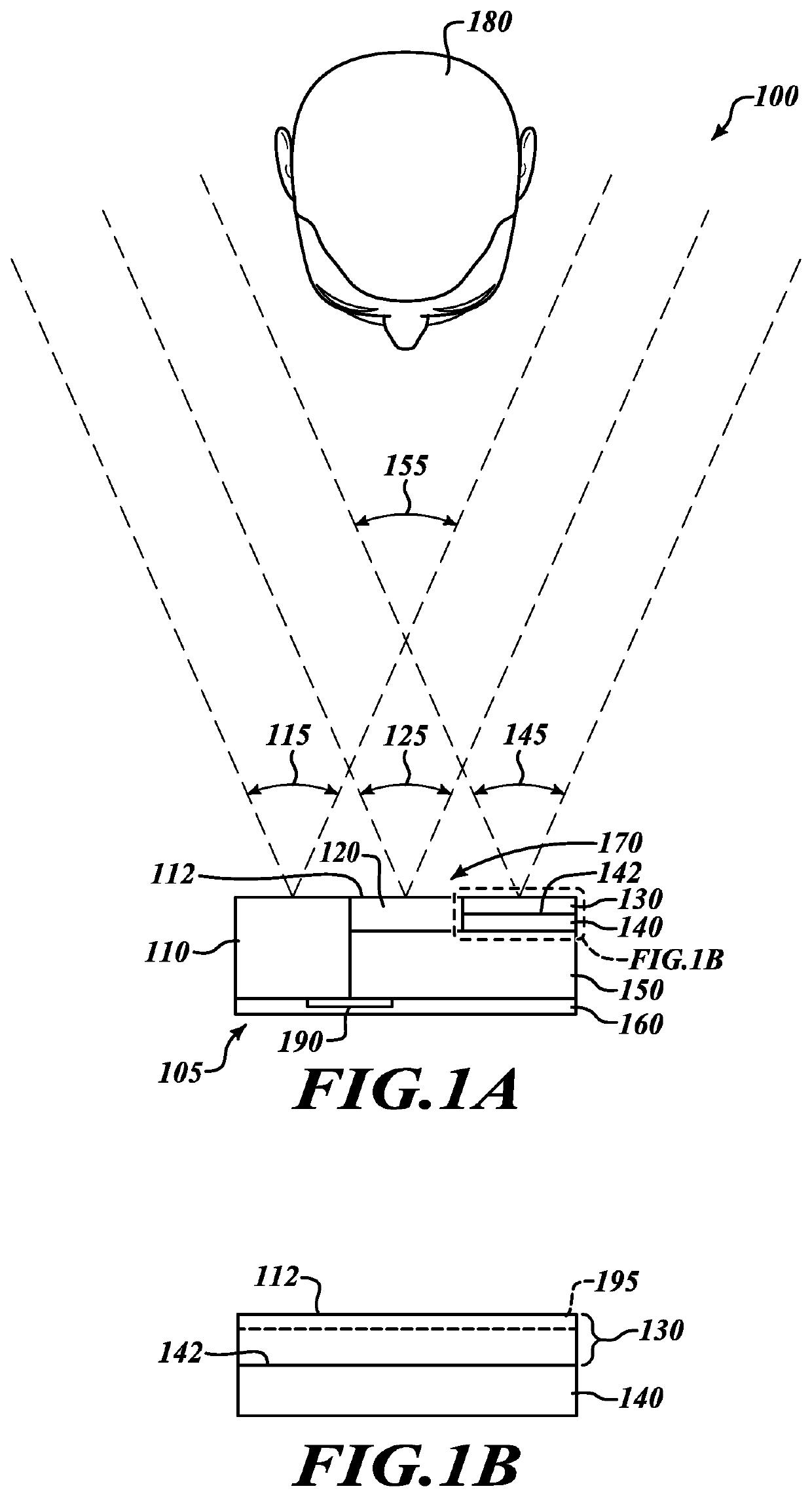
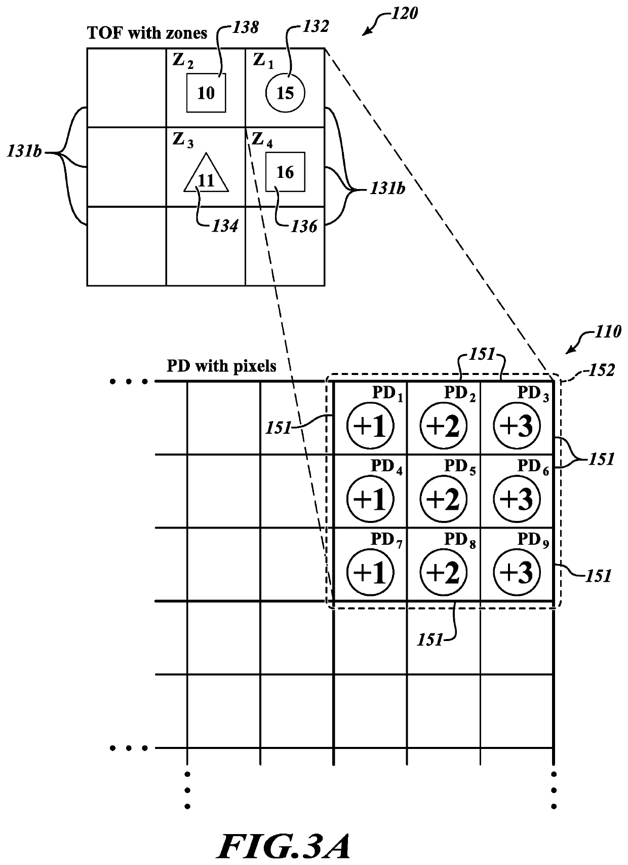
[0003]The present disclosure provides a cost effective, low power, and accurate solution for depth sensing by utilizing a combination of a ranging sensor and an image sensor. One example of the ranging sensor includes a time of flight (ToF) sensor which can accurately detect a distance from the sensor to an object or objects being imaged. The image sensor includes a sensor having a phase detection function, phase detect autofocus function, or similar functions. While the ToF sensor provides a relatively low resolution and an absolute depth map, the image sensor provides a relatively high resolution and a relative depth map. By combining sensor data from the ToF sensor and the phase information from the image sensor, accurate depth information with high resolution is obtainable.

Problems solved by technology

However, using multiple cameras can drive up the cost.
Dual cameras also have problems, which include: a relatively high error rate (e.g., conventional dual cameras exhibit error rates around 10-30% which is high considering the industries standard), alignment issues, drift issues (e.g., voltage and thermal problems) and dead zone issues (e.g., dead zones created between cameras).

Method used


Image

  • Depth sensing with a ranging sensor and an image sensor
  • Depth sensing with a ranging sensor and an image sensor
  • Depth sensing with a ranging sensor and an image sensor

Examples


Embodiment Construction

[0017]In the following description, certain specific details are set forth in order to provide a thorough understanding of various disclosed embodiments. However, one skilled in the relevant art will recognize that embodiments may be practiced without one or more of these specific details, or with other methods, components, materials, etc. In other instances, well-known structures or methods associated with time of flight sensors and phase detection sensors have not been shown or described in detail to avoid unnecessarily obscuring descriptions of the embodiments.

[0018]Unless the context indicates otherwise, throughout the specification and claims which follow, the word “comprise” and variations thereof, such as, “comprises” and “comprising” are to be construed in an open, inclusive sense that is as “including, but not limited to.” Further, the terms “first,”“second,” and similar indicators of the sequence are to be construed as interchangeable unless the context clearly dictates ot...


PUM


Abstract

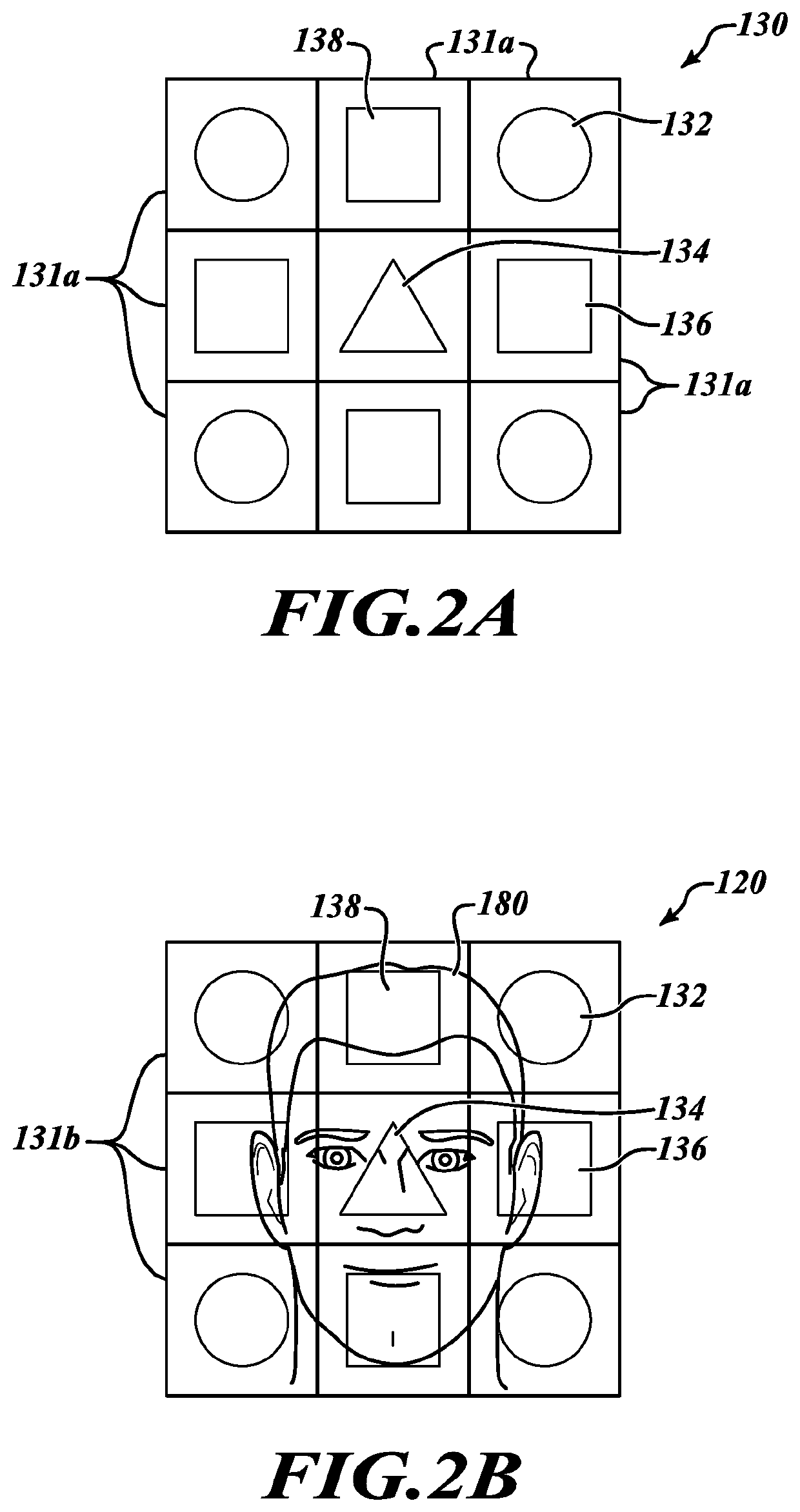
The present disclosure provides a device and method for depth sensing by utilizing the combination of a ranging sensor and an image sensor. The ranging sensor can accurately detect distance measurement from an object. The image sensor can take images with high resolution of the object. By combining each sensor data from the ranging sensor and the image sensor, accurate depth information with high resolution of the object may be obtained. A structured light having patterned shapes are used in conjunction with the ranging sensor to receive reflected patterned shapes of the object. These reflected patterned shapes are used to analyze distance measurements associated with the specific patterned shapes. These distance measurements from both the ranging sensor and the image sensor is aligned and combined to generate an accurate depth map with high resolution using a processor of an electronic device including the ranging sensor and the image sensor.

Description

BACKGROUNDTechnical Field[0001]The present disclosure is directed to generating depth information of an object in a field of view.Description of the Related Art[0002]Depth information has become important in many aspects of current technology. Some image sensors provide distance information with a captured image. The distance information being a distance from a lens of the sensor to an object, as an example. Applications of depth information extend to computer vision, machine learning, and artificial intelligence, among others. For example, depth sensing can be used in augmented reality (AR), virtual reality (VR), and environment mapping. Dual cameras have been used for depth sensing to obtain depth information. However, using multiple cameras can drive up the cost. Dual cameras also have problems, which include: a relatively high error rate (e.g., conventional dual cameras exhibit error rates around 10-30% which is high considering the industries standard), alignment issues, drift ...

Claims


Application Information

Patent Timeline
Patent Type & Authority Patents(United States)
IPC IPC(8): G06T7/521
CPCG06T7/521G06T2207/10028G06T7/33G06T2207/30201
Inventor YANG, XIAOYONGRYU, CHANG MYUNGKATH, JAMESXIAO, RUI
Owner STMICROELECTRONICS SRL
Learn More