Lens unit
a technology for lenses and holder, applied in the direction of mountings, instruments, camera body details, etc., can solve the problems of caulking part tip end side damage, etc., and achieve the effect of enhancing the waterproof performance between the first lens and the holder
- Summary
- Abstract
- Description
- Claims
- Application Information
AI Technical Summary
Benefits of technology
Problems solved by technology
Method used
Image
Examples
first embodiment
(Structure of Lens Unit)
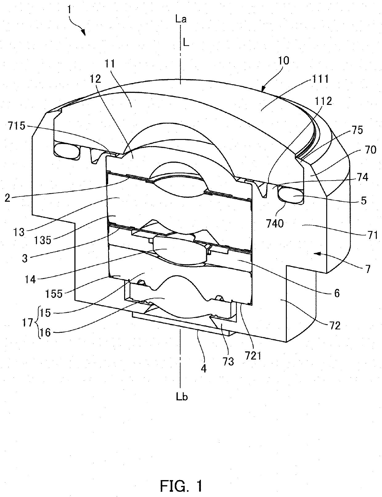
[0030]FIG. 1 is a perspective view showing a lens unit 1 in accordance with a first embodiment of the present invention in which a part of the lens unit 1 is cut out and viewed from an object side. As shown in FIG. 1, a lens unit 1 in this embodiment includes a wide-angle lens 10 comprised of a plurality of lenses disposed in an optical axis “L” direction and a tube-shaped holder 7 which holds the wide-angle lens 10 on an inner side, and the lens unit 1 is used in an optical device such as an imaging device. In this embodiment, the holder 7 is made of light shielding resin.
[0031]The wide-angle lens 10 has, for example, a 5-group 6-piece lens configuration. More specifically, the wide-angle lens 10 is, from the object side “La” (object to be photographed side / front side) toward the image side “Lb”, configured of a first lens 11 having negative power, a second lens 12 having negative power, a third lens 13 having positive or negative power, a fourth lens 14 hav...
second embodiment
[0047]FIG. 4 is an enlarged cross-sectional view showing surroundings of a caulked part 75 to a first lens 11 of a lens unit 1 in accordance with a second embodiment of the present invention. In each of this embodiment and embodiments described below, basic configurations are the same as each other and thus, the same reference signs are used in common portions and their descriptions are omitted.
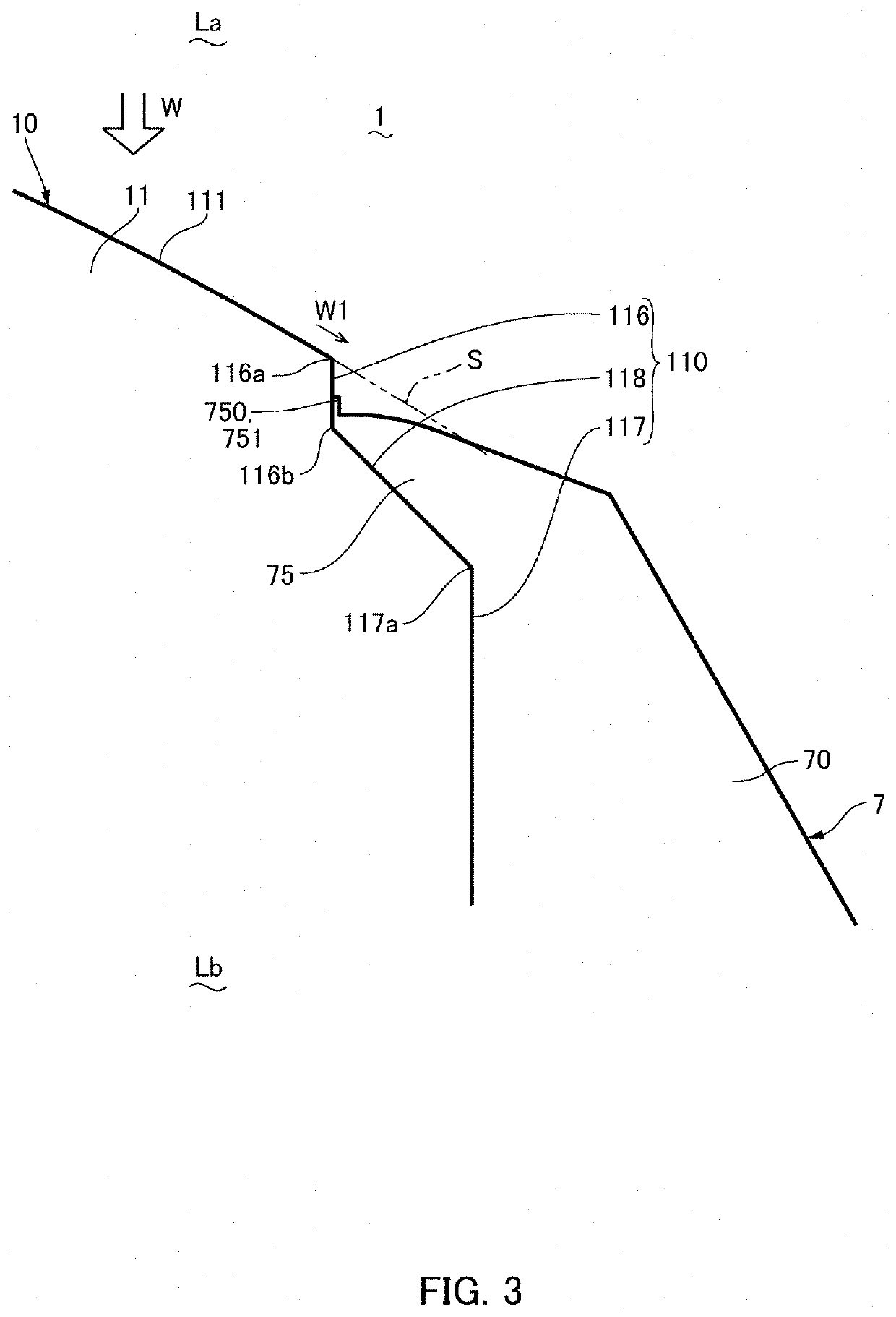
[0048]In the first embodiment, the protruded part 751 formed in the inner side end part 750 in the radial direction of the caulked part 75 is extremely thin in comparison with the other portion of the caulked part 75. However, as shown in FIG. 4, a configuration may be adopted that a protruded part 751 is comparatively thick and an outer peripheral face of the protruded part 751 is formed to be an inclined face. Also in this case, the protruded part 751 is located on the image side “Lb” with respect to a virtual extended face “S” which is obtained by extending an object side “La” face (first ...
third embodiment
[0049]FIG. 5 is an enlarged cross-sectional view showing surroundings of a caulked part 75 to a first lens 11 of a lens unit 1 in accordance with a third embodiment of the present invention. In the first and second embodiments, the inner side end part 750 in the radial direction of the caulked part 75 covers the first side face part 116 from an outer side in the radial direction. However, as shown in FIG. 5, an inner side end part 750 in the radial direction of a caulked part 75 may be located at a position separated toward an outer side in the radial direction from a first side face part 116. Also in this embodiment, the inner side end part 750 in the radial direction of the caulked part 75 is located on the image side “Lb” with respect to a virtual extended face “S” which is obtained by extending a first face 111 to an outer side in the radial direction. Therefore, similar effects to the first embodiment are attained, for example, when a high pressure water flow “W” is ejected to ...
PUM
 Abstract
Description
Claims
Application Information
 - R&D
- Intellectual Property
- Life Sciences
- Materials
- Tech Scout
- Unparalleled Data Quality
- Higher Quality Content
- 60% Fewer Hallucinations
Browse by: Latest US Patents, China's latest patents, Technical Efficacy Thesaurus, Application Domain, Technology Topic, Popular Technical Reports.
© 2025 PatSnap. All rights reserved.Legal|Privacy policy|Modern Slavery Act Transparency Statement|Sitemap|About US| Contact US: help@patsnap.com


