
Power supply circuit and photovoltaic power generation system comprising same

a power supply circuit and photovoltaic technology, applied in the direction of dc-dc conversion, dc-dc conversion, ac network voltage adjustment, etc., can solve the problems of short circuit current, low fill factor (ff), and components working at high voltage for a long time, and achieve low cost, simple realization, and small radiation to the environment

Active Publication Date: 2022-06-14
MORNSUN GUANGZHOU SCI & TECH
View PDF11 Cites 0 Cited by
  • Summary
  • Abstract
  • Description
  • Claims
  • Application Information

AI Technical Summary

Benefits of technology

[0020]In view of this, the technical problem to be solved by the disclosure is to provide a power supply circuit and a photovoltaic power generation system including the power supply circuit. The output voltage of the power supply circuit has a small change in AU / At, so the photovoltaic power generation system using the power supply circuit is environmentally friendly and causes less pollution.
[0047](1) The voltage waveform AU / At output by the power supply circuit is small, so that the service life of the photovoltaic string in the photovoltaic power generation system using the power supply circuit is prolonged, and the radiation to the environment is small.
[0048](2) The circuit is simple to realize, low in cost, high in reliability, and low in energy consumption.

Problems solved by technology

The components work at high voltage for a long time, and there is leakage current between the cover glass, encapsulation material, and frames.
A large amount of charge accumulates on the surface of the cell, which deteriorates the passivation effect of the cell surface, resulting in a decrease in the fill factor (FF), short circuit current (Isc), and open circuit voltage (Voc), making the performance of components lower than the designed standard.
Since 2012, component quality problems caused by PID have been raised frequently in photovoltaic power plants, and the PID phenomenon has thus received a lot of attention.
According to the introduction of the third-party testing agency, PID means that when the solar component forms a high-strength negative voltage with the ground, the resulting potential difference will not only cause damage to the solar cell or module, but also cause the problem of power generation efficiency degradation.
The severe effect caused by PID can directly reduce the investment yield of photovoltaic power plants.
However, there is no specific implementation method for the voltage compensation device, and it is only proposed that the function of the voltage compensation device is to output pulse voltage.
The three kinds of pulse voltages AU / At change dramatically, which will cause the photovoltaic string to peel off and crack, and the service life will be decreased.
Because it is difficult to use the photovoltaic string to achieve electromagnetic shielding, the impact caused by electromagnetic radiation on the environment is significant.
Although photovoltaic facilities are mostly installed in uninhabited areas, there is a great level of electromagnetic radiation, and the reflection of the ionosphere in the atmosphere still causes great electromagnetic environmental pollution.
Besides, the cost of obtaining these three waveforms is not low.
If a square wave is output, there will be electromagnetic pollution to the environment due to a high content of harmonic components.

Method used


Image

  • Power supply circuit and photovoltaic power generation system comprising same
  • Power supply circuit and photovoltaic power generation system comprising same
  • Power supply circuit and photovoltaic power generation system comprising same

Examples


first embodiment

The First Embodiment

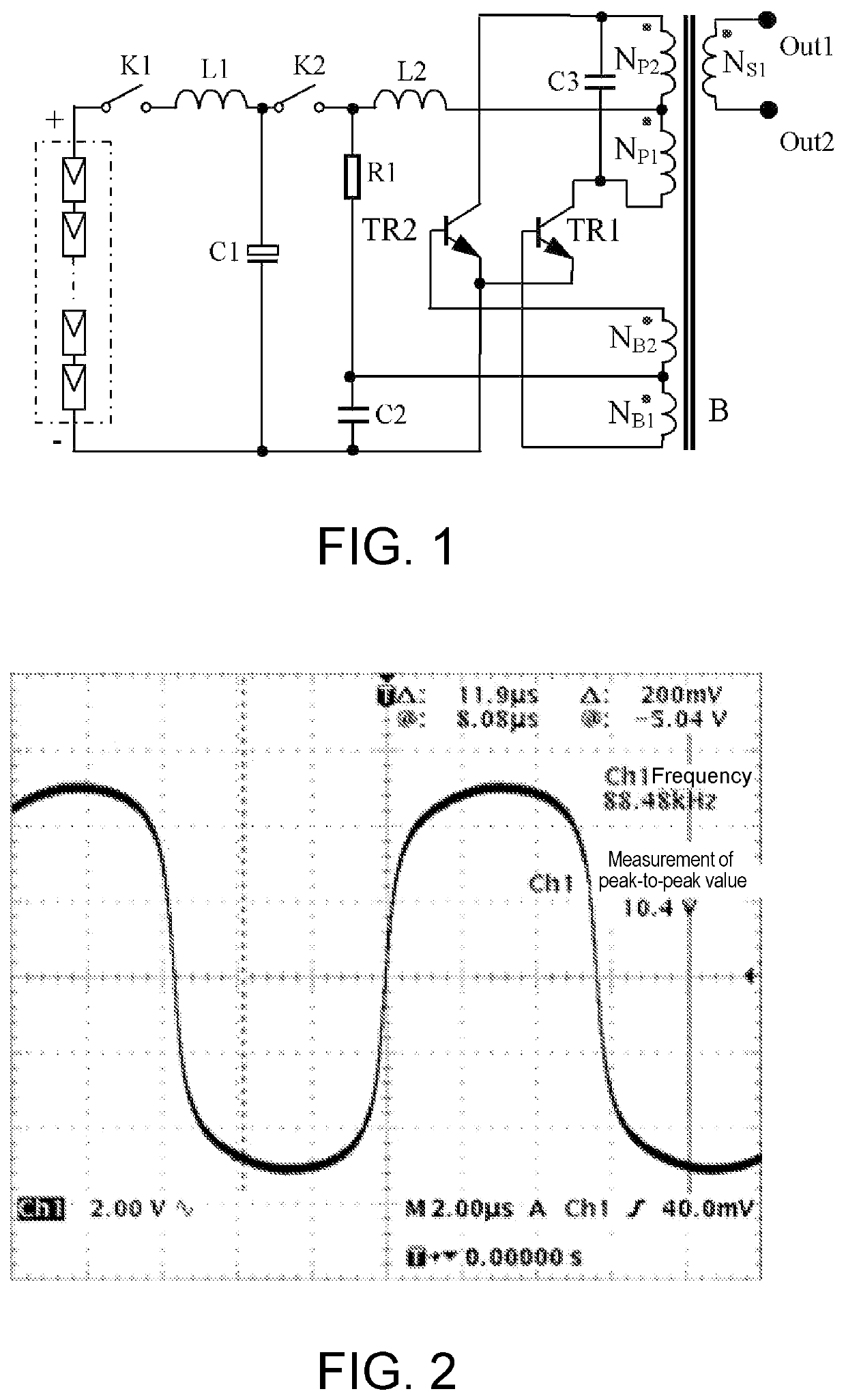
[0057]Please refer to FIG. 1, FIG. 1 is a schematic diagram showing the principle of a power supply circuit according to a first embodiment of the disclosure. The configuration of components and connection relations are as follows:

[0058]The power supply circuit shown in FIG. 1 includes a switch K1, an inductor L1, a capacitor C1, a switch K2, and a CCFL conversion circuit.

[0059]One end of the switch K1 is the positive input terminal of the power supply circuit, the other end of the switch K1 is connected to one end of the inductor L1. The other end of the inductor L1 is simultaneously connected to one end of the capacitor C1 and one end of the switch K2, and the other end of the capacitor C1 is the negative input terminal of the power supply circuit. The positive input terminal of the CCFL conversion circuit is connected to the other end of the switch K2, the negative input terminal of the CCFL conversion circuit is connected to the negative input terminal of the...

second embodiment

The Second Embodiment

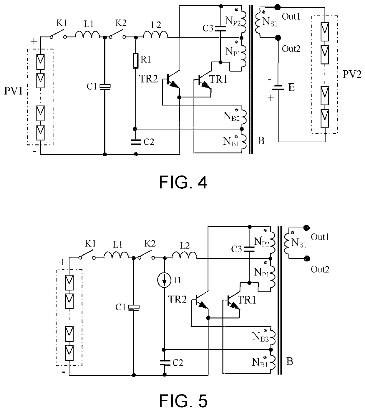
[0088]FIG. 4 is a schematic diagram showing the principle of the improved photovoltaic power generation system applied to the power supply circuit according to the second embodiment of the disclosure. Since the equivalent inside the photovoltaic string has a diode connected in series, and in order to improve the activation effect, a set of DC power supply E is connected in series at the output terminal of the power supply circuit, that is, a set of DC power supply E is connected in series with the photovoltaic string. The series connection method is one of the following two:

[0089](1) The negative pole of the DC power supply is electrically connected to the second output terminal of the power supply circuit, the first output terminal of the power supply circuit is electrically connected to the positive pole of the photovoltaic string, and the negative pole of the photovoltaic string is electrically connected to the positive pole of the DC power supply.

[0090](2) T...

third embodiment

The Third Embodiment

[0094]FIG. 5 is a schematic diagram showing the principle of a power supply circuit according to a third embodiment of the disclosure. The third embodiment is different from the first embodiment in that the resistor R1 is replaced with a constant current source, and the current direction is the same. In this way, when the input voltage drops, due to the presence of the constant current source, it is possible to achieve that the current supplied by the CCFL conversion circuit to the bases of the two push-pull triodes TR1 and TR2 is constantly unchanged. Therefore, the input voltage of the power supply circuit can be wider. As mentioned above, when the operating voltage drops from 377V to 60V, since the base current supplied by the constant current source to the triodes TR1 or TR2 is not reduced, the CCFL converter will not stop oscillating so as to adapt to the wide-range terminal voltage of the photovoltaic string. The working principle of this embodiment and its...


PUM

PropertyMeasurementUnit
voltageaaaaaaaaaa
voltageaaaaaaaaaa
lengthaaaaaaaaaa

Abstract

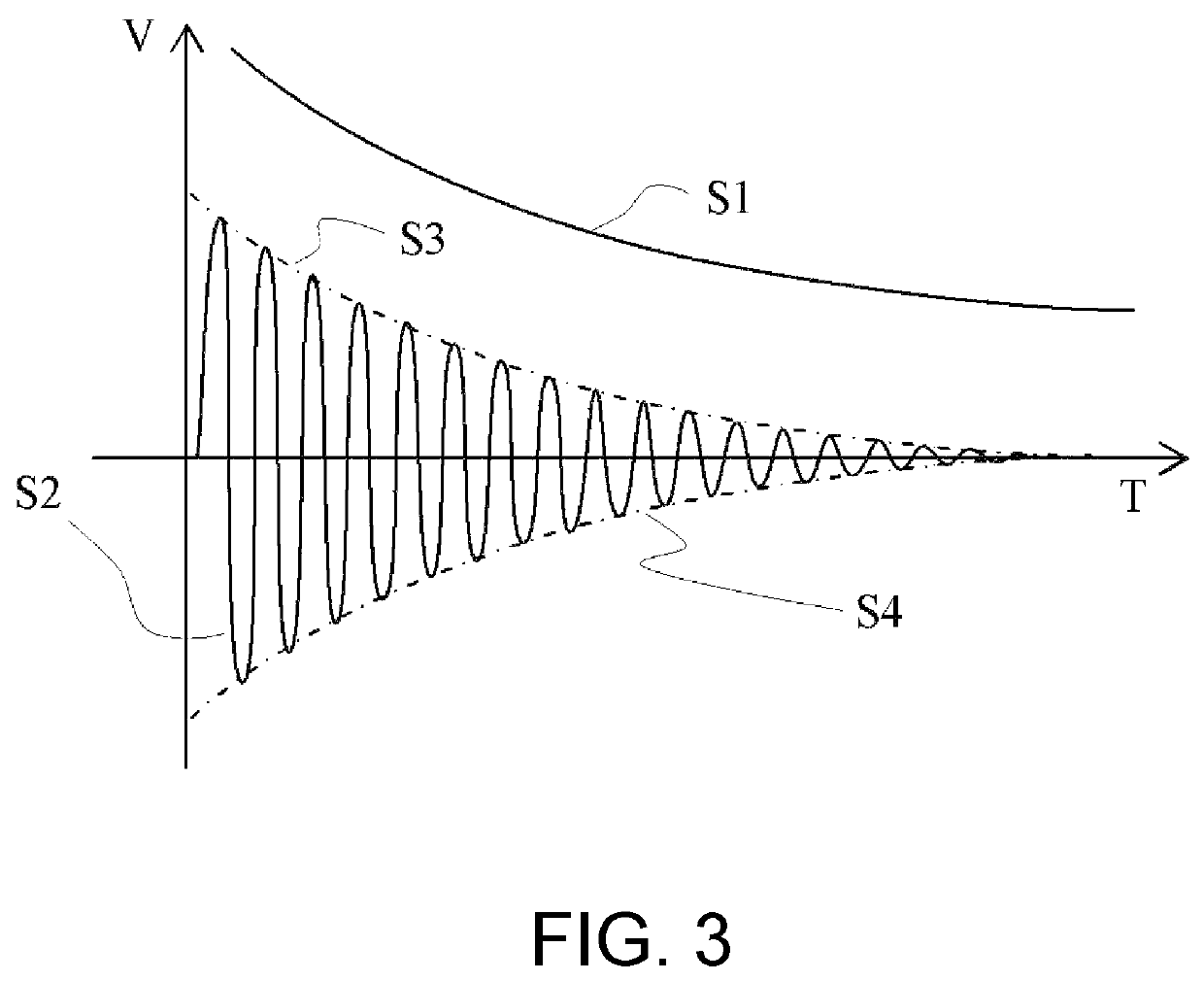
A power supply circuit and a photovoltaic power generation system comprising same. The power supply circuit utilizes the condition that a voltage output by discharge of a capacitor is a direct-current voltage which decreases with time, a CCFL conversion circuit is connected behind the capacitor, the CCFL conversion circuit converts the input direct-current voltage which decreases which time into a sinusoidal alternating-current for output. Since the CCFL conversion circuit operates in an open-loop mode, a peak-to-peak value of the sinusoidal alternating-current output by the CCFL conversion circuit is in direct proportion to an operating voltage of the CCFL conversion circuit, the voltage decreases with time, that is, the peak-to-peak valve of the sinusoidal alternating-current output by the CCFL conversion circuit decreases with time, thus, an effective value of the sinusoidal alternating-current decreases with time, and an attenuated sinusoidal alternating-current voltage is obtained.

Description

CROSS-REFERENCE TO RELATED APPLICATION[0001]This application is a 371 of international application of PCT application serial no. PCT / CN2019 / 119639, filed on Nov. 20, 2019, which claims the priority benefits of China application no. 201811533242.1, filed on Dec. 14, 2018. The entirety of each of the above-mentioned patent applications is hereby incorporated by reference herein and made a part of this specification.BACKGROUNDTechnical Field[0002]The disclosure relates to a power supply circuit used in a photovoltaic power generation system, in particular to a power supply circuit for activating aging photovoltaic strings.Description of Related Art[0003]With the anticipated depletion of petrochemical energy and the environmental pollution it brings, the research and application of renewable clean energy are highly valued by countries all over the world. Specifically, wind power and photovoltaic power generation technology have become the popular research topics. Photovoltaic power gene...

Claims


Application Information

Patent Timeline
Patent Type & Authority Patents(United States)
IPC IPC(8): H02S40/32H02M7/538H02J3/12
CPCH02M7/538H02J3/12H02S40/32H02J2300/24H02M3/33569H02M3/3376H02S40/30Y02E10/56H02M1/36H02M1/0048H02M3/3382Y02B70/10
Inventor WANG, BAOJUN
Owner MORNSUN GUANGZHOU SCI & TECH
Learn More