Hybrid venous reservoir

a technology of venous reservoir and hybrid venous, which is applied in the direction of suction devices, other blood circulation devices, medical devices, etc., can solve the problems of large volume of clean blood and large volume of air in the “shut-off” design

Active Publication Date: 2022-06-14
TAMARI YEHUDA
View PDF3 Cites 0 Cited by
  • Summary
  • Abstract
  • Description
  • Claims
  • Application Information

AI Technical Summary

Benefits of technology

[0011]Feature 5 described in reference to FIG. 5a of patent '440 requires blood to flow from outlet 4 of air purger chamber 1116 to inlet 5 of compliant storage chamber 1103 via fluid communication 4b. That flow is by gravity and requires a large ID (e.g., ⅝″) and must flow through CSC 1103. See FIG. 4a of aforementioned U.S. Pat. No. 7,591,812. With the current invention venous blood is pulled from the APC by pump 20 via conduit 16 and does not flow through the CSC. See FIG. 1c. In addition, the present HVR eliminates inlet 5 of prior art shown in FIG. 1b and allows for complete emptying of the reservoir at the end of the case when the patient is taken off CPB. In Tamari's aforementioned earlier patents, the venous reservoir retains the volume in the reservoir below line B-B′ shown in FIG. 1b and height y1 in FIG. 4a of aforementioned U.S. Pat. No. 7,591,812.
[0012]It is the objective of the present HVR to utilize the unique features of the venous reservoir according to Tamari's U.S. Pat. Nos. 7,591,812, 8,147,440, and 8,882,696 but reduce its prime volume, its operating volume and allow it to empty completely at the end of the case.

Problems solved by technology

However, the “shut-off” design requires additional volume (see FIG. 5a of Tamari's U.S. patent '812).
Clean blood may entrain a large volume of air.

Method used


Image

  • Hybrid venous reservoir
  • Hybrid venous reservoir
  • Hybrid venous reservoir

Examples


Embodiment Construction

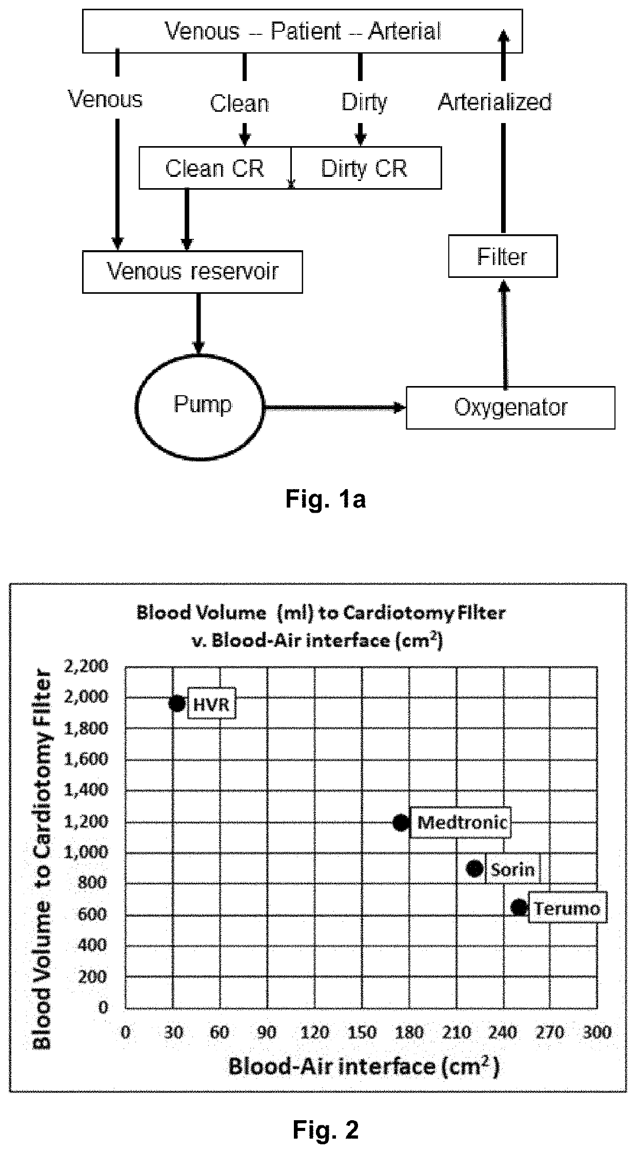
[0023]Reference should now be made to the drawings wherein the same reference numerals are used throughout to designate the same or similar parts. It should be noted that the use of cardiopulmonary bypass, as shown in FIG. 1a is for descriptive purposes and should not be taken as a limitation to the use of the device described hereinafter and is only for illustrative purposes. Other embodiments are possible and, therefore, what follows is suggestive of the art and should not be construed as a limitation of the scope or the spirit of the invention.

[0024]FIG. 1a is a schematic representation of a typical cardiopulmonary bypass circuit as routinely practiced. Here blood flows from the venous side of a patient placed on CPB into a venous reservoir used to store venous blood and eliminate air entrapped in the venous blood. The blood is pumped from the reservoir through an oxygenator (i.e., an artificial lung) that removes CO2 and adds O2 and onward through an arterial filter and back to ...


PUM


Abstract

The invention is an innovative hybrid venous reservoir designed to receive and store blood during cardiopulmonary bypass (CPB), the hybrid venous reservoir consisting of an air purging chamber that limits air in the venous blood entering the air purging chamber from exiting the air purging chamber in combination with a compliant storage chamber with at least one pliable wall, the combination providing a large volume capacity while limiting the area of the blood-air interface to that of the air purging chamber.

Description

BACKGROUND OF THE INVENTIONField of the Invention[0001]Venous reservoirs are an essential component of the cardiopulmonary bypass (CPB) circuit adopted to support patients by the heart lung machine. FIG. 1a is a line drawing summarizing the different components of a CPB circuit. As shown, blood flows from the venous side of the patient to a venous reservoir and then is pulled from the reservoir by an arterial pump that pushes the blood to an oxygenator, then through an arterial filter and finally back to the arterial side of the patient. Blood collected from the surgical field (“dirty” blood) and from the circuit or patient (“clean” blood) must be debubbled and filtered prior to returning it back to the patient. The latter is accomplished by a cardiotomy reservoir shown as “CR” in FIG. 1a. The venous reservoir serves to trap and remove air bubbles from venous blood flowing into it and provide volumetric compliance to accommodate variations in the blood volume circulating in the extr...

Claims


Application Information

Patent Timeline
Patent Type & Authority Patents(United States)
IPC IPC(8): A61M1/36
CPCA61M1/3632A61M1/3638A61M1/3666A61M2205/0216A61M2205/7527A61M1/3667
Inventor TAMARI, YEHUDA
Owner TAMARI YEHUDA
Why Eureka
Try Eureka