Method of evaluating level of cleanliness of hollow fiber membrane device, method of washing hollow fiber membrane device, and washing device for hollow fiber membrane device

a technology of filter membrane and level of cleanliness, which is applied in the direction of multi-stage water/sewage treatment, water/sewage treatment by degassing, instruments, etc., can solve the problems of inability the contaminated filter membrane device itself, and the inability to apply the method to evaluate the level of cleanliness of the filter membrane device. to achieve the effect of evaluating the level of cleanliness of the hollow fiber membrane devi

Active Publication Date: 2022-06-07
ORGANO CORP
View PDF18 Cites 0 Cited by
  • Summary
  • Abstract
  • Description
  • Claims
  • Application Information

AI Technical Summary

Benefits of technology

[0008]According to the present invention, ultrapure water is permeated through the hollow fiber membrane device, and fine particles that are contained in the permeating water are captured by the first filter membrane. Determination can be made whether or not the hollow fiber membrane device has a predetermined level of cleanliness by analyzing the number and properties of the fine particles that are contained in the permeating water. Therefore, accordingly to the present invention, it is possible to evaluate the level of cleanliness of the hollow fiber membrane device before it is installed in an ultrapure water production system.

Problems solved by technology

The method described in JP2014-194359A is directed to capturing and analyzing fine particles that are contained in the sample water, but the level of cleanliness of the hollow fiber membrane device itself cannot be evaluated.
The method described in JP2013-031835A involves intentionally causing a filter membrane device to capture fine metal particles, but as a result, the filter membrane device itself is contaminated with the fine metal particles.
Thus, this method cannot be applied to evaluation of the level of cleanliness of a filter membrane device before it is installed in an ultrapure water production system.

Method used


Image

  • Method of evaluating level of cleanliness of hollow fiber membrane device, method of washing hollow fiber membrane device, and washing device for hollow fiber membrane device
  • Method of evaluating level of cleanliness of hollow fiber membrane device, method of washing hollow fiber membrane device, and washing device for hollow fiber membrane device
  • Method of evaluating level of cleanliness of hollow fiber membrane device, method of washing hollow fiber membrane device, and washing device for hollow fiber membrane device

Examples


Embodiment Construction

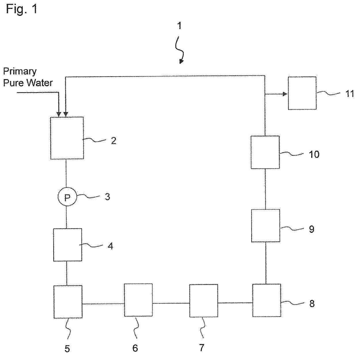
[0027]Embodiments of the present invention will be described hereinbelow with reference to the drawings. FIG. 1 illustrates an exemplary configuration of ultrapure water production system 1, to which the present invention is applied. Ultrapure water production system 1 includes primary pure water tank 2, pump 3, heat exchanger 4, ultraviolet oxidation device 5, hydrogenation device 6, catalytic reaction device 7, non-regenerative mixed bed ion exchange device (cartridge polisher) 8, membrane degassing device 9 and ultrafiltration membrane device 10. These components constitute a secondary pure water system (subsystem), which performs a series of processes on primary pure water that is produced by a primary pure water system (not shown) in order to produce ultrapure water, and supplies the ultrapure water to point of use 11.

[0028]Water to be treated (primary pure water) that is stored in primary pure water tank 2 is fed by pump 3 and is supplied to heat exchanger 4. The water to be t...


PUM

PropertyMeasurementUnit
pore diameteraaaaaaaaaa
particle sizeaaaaaaaaaa

Abstract

The level of cleanliness of a hollow fiber membrane device is evaluated before it is installed in an ultrapure water production system. A method of evaluating the level of cleanliness of the hollow fiber membrane device includes capturing fine particles in permeating water by means of a first filter membrane, wherein the permeating water is ultrapure water that permeates through the hollow fiber membrane device before the hollow fiber membrane device is installed in an ultrapure water production system; and analyzing the fine particles that are captured by the filter membrane.

Description

TECHNICAL FIELD[0001]The present application is based upon and claims priority from Japanese Patent Application No. 2017-44836 filed on Mar. 9, 2017, the disclosure of which is hereby incorporated by reference herein in its entirety.[0002]The present invention relates to a method of evaluating the level of cleanliness of a hollow fiber membrane device, a method of washing a hollow fiber membrane device, and a washing device for a hollow fiber membrane device, particularly to a method of evaluating the level of cleanliness of an ultrafiltration membrane device that is washed before it is installed in an ultrapure water production system.BACKGROUND ART[0003]A hollow fiber membrane device, such as an ultrafiltration membrane device, is installed at the end of an ultrapure water production system in order to remove fine particles. Hollow fiber membranes can be installed with higher density than flat membranes and pleated membranes, and can increase the volume of permeating water per mod...

Claims


Application Information

Patent Timeline
Patent Type & Authority Patents(United States)
IPC IPC(8): B01D65/10B01D61/14B01D61/20B01D65/02B01D69/08C02F1/44G01N15/08C02F103/04
CPCB01D65/10B01D61/145B01D61/20B01D65/02B01D69/08C02F1/444G01N15/0806C02F2103/04G01N2015/086B01D63/02G01N23/02G01N23/2251G01N23/2252C02F9/00C02F1/32C02F1/725C02F1/42C02F2001/427C02F1/20C02F1/70C02F2303/16C02F2209/105G01N2015/084B01D2321/44G01N15/08B01D2321/00
Inventor ICHIHARA, FUMITAKASUGAWARA, HIROSHI
Owner ORGANO CORP
Why Eureka
Try Eureka