Eureka AIR delivers breakthrough ideas for toughest innovation challenges, trusted by R&D personnel around the world.

Enema device, and a delivery container for use in said enema device

a technology of enema and delivery container, which is applied in the direction of enemata/irrigator, medical syringe, syringe, etc., can solve the problems of discomfort and irritation, enema dispenser affects the ease with which a user may administer liquid, and it is difficult for patients with poor dexterity to self-administrate enema, so as to achieve safe and effective administration of enema to patients.

Active Publication Date: 2022-05-24
MBH INT AS
View PDF16 Cites 1 Cited by
  • Summary
  • Abstract
  • Description
  • Claims
  • Application Information

AI Technical Summary

Benefits of technology

[0015]It is therefore a first aspect of the present invention to provide a handheld enema device that safely and effectively can administer an enema to a patient without causing discomfort.
[0016]It is a second aspect of the present invention to provide an enema device where the liquid is easier to administer, and where air effectively is prevented from being mixed with the enema.
[0017]It is a third aspect of the present invention to provide an enema device in which an effective dosage of enema can be administered without required reloading of the delivery container.

Problems solved by technology

The applicator nozzle of this type of conventional enema application device often causes discomfort and irritation when being inserted.
Furthermore, the force required to squeeze the liquid from an enema dispenser affects the ease with which a user may administer the liquid.
The self-administration of a conventional enema may be especially difficult for patients have poor dexterity, e.g. due to the squeeze force required to deliver a complete dose of the enema liquid.
Although it would be advantageous to decrease the amount of squeeze force required to administer an enema, such a modification may adversely affect other desirable features of the device.
A simple reduction in the resistance to flow of the liquid through the device may compromise these features.
However, it is often difficult for the patient to administer the enema to him or herself since the applicator nozzle not only must be inserted into a sensitive area, but the administration position is also inconvenient for the user making it is difficult for the patient to administer the liquid while steadily holding the enema in the required area.
Often the patient is assisted by another individual; however, assistance may not always be available, if, for instance, the patient lives alone.
The latter will ensure that the device can be used for several administrations as needed by the user, however studies and user feed-back have shown that most user can not get a convenient grip on the delivery container, nor does they not have the strength to provide a constant pressure on the delivery container.
However, when pressure is released on the delivery container, air will unintentionally be drawn into the container and mixed with the enema.
This will cause uncomfortable distending of the colon causing pain and cramps.
Thus, in order to avoid intake of air, the user will have to apply a constant pressure to the delivery container during the administrating procedure, which may be difficult for users / patients having weak fingers, e.g. due to arthritis or the like.
Furthermore, as air drawn into the container, expelling of the enema becomes increasingly more difficult.
However, ensuring such an orientation is almost impossible as the enema often is administered on the toilet or in the bed, where the user's / patient's position prevents such an orientation.
Since administration of air will cause discomfort several reloadings of the container with enema are often required in order to deliver an effective dosage of enema and at the same time prevent delivery of air.
However, reloading of the container requires easy access to the enema.
Thus, the user has to have a reservoir of enema nearby in order to provide easy reloading, making the reloading both difficult and troublesome.

Method used


Image

  • Enema device, and a delivery container for use in said enema device
  • Enema device, and a delivery container for use in said enema device
  • Enema device, and a delivery container for use in said enema device

Examples


first embodiment

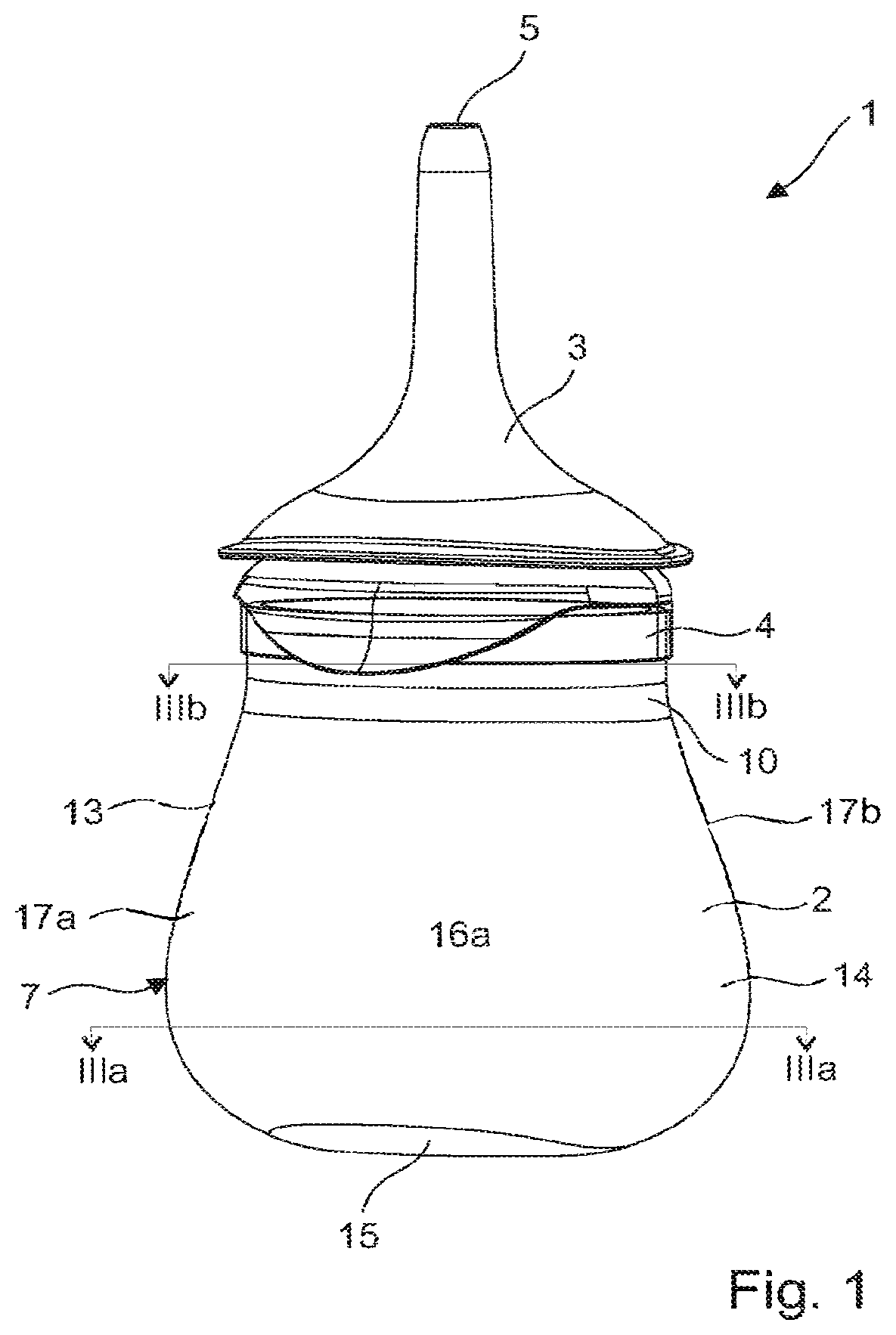
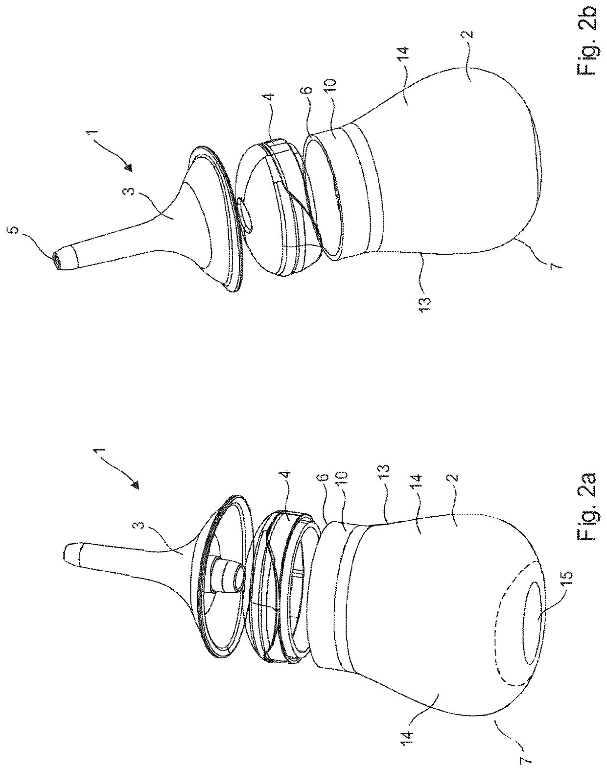
[0076]FIG. 1. is a schematic view of the enema device 1 according to the invention, and FIG. 2 is the same in an exploded view. Said device consist basically of an enema delivery container 2, arranged as a hand held pump having a cross-section that is substantially oval, an applicator nozzle 3 and a closure member 4. The applicator nozzle 3 has an exit opening 5 through which the enema can be expelled when pressure is applied to the delivery container 2.

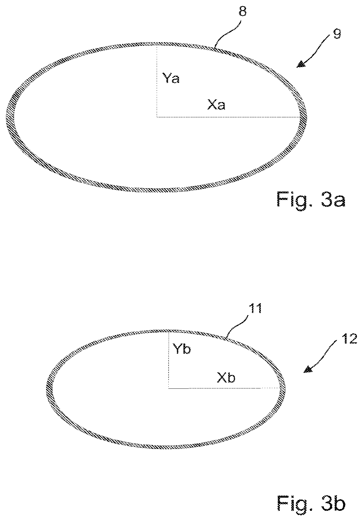
[0077]In the embodiment shown in FIG. 1 and FIG. 2 the delivery container 2 comprises an opening 6, a bottom section 7 with a first cross-section 8 in the shape of a first oval 9, and a) section 10 with a second cross-section 11 in the shape of a second oval 12. FIG. 3a shows the first oval taken along the lines IIIa-IIIa in FIG. 1, and FIG. 3b shows the second oval 12 taken along the lines IIIb-IIIb of FIG. 1.

[0078]The major axis Xa and the minor axis Ya of said first oval 9 is larger than the major axis Xb and the minor axis Yb of ...

third embodiment

[0094]FIG. 7 shows the delivery container 2″ according to the invention, in which the compression zones 40 are provided by reducing the wall thickness X of the delivery container in two bending lines 44 arranged at one of the long curved surfaces 16a, a cross section 45 taken along the lines VIII-VIII is shown in FIG. 8a. The bending lines are shaped as a V, see enlarged view of a bending line in FIG. 8b, have the same cutting angle α, and the same depths d, i.e. the characteristics of the bending lines are the same for the two bending lines 44. However a person skilled in the art will understand that said bending lines and / or the shape of the bending line and / or the depth (wall thickness) and / or cutting angles of said bending lines may vary in order to adjust the required bending force of the compression zones. Furthermore, the number of bending lines and / or placement of said bending lines may be adjusted.

[0095]Alternatively, the compression zones may be provided by providing reinf...


PUM


Abstract

The present invention relates to an enema device comprising a delivery container arranged for accommodating an enema and an applicator nozzle for dispersing the enema, and wherein the delivery container is arranged as a hand held pump and wherein a cross-section of said delivery container has the shape of an oval. Thereby is provided a simple, inexpensive and essentially maintenance free enema device which can be used for self-administrating of an enema.

Description

CLAIM OF BENEFIT TO PRIOR APPLICATIONS[0001]This application is a 371 filing of International Patent Application PCT / DK2019 / 050291 filed Oct. 2, 2019, which claims priority to Danish patent application PA2018 / 70651 filed Oct. 3, 2018.TECHNICAL FIELD[0002]The present invention relates to an enema device comprising a flexible delivery container and an applicator nozzle.BACKGROUND[0003]Administrating an enema is a common medical procedure whereby fluid is injected into the rectum and lower intestine of a patient in order to induce bowel movement. The need for such a procedure typically arises in patients suffering from certain physical ailments in which voluntary bowel control is impaired or when the bowel needs to be cleaned before e.g. a coloscopy or a surgical operation.[0004]Medical equipment currently exists in the art for administering an enema to patients in need of this procedure. At least one type of equipment consists of an enema squeeze bottle filled with the fluid intended ...

Claims


Application Information

Patent Timeline
Patent Type & Authority Patents(United States)
IPC IPC(8): A61M3/02
CPCA61M3/0262A61M3/0245A61M3/0279A61M39/24
Inventor HAGEN, THIT ROSEANDERSEN, BIRTHE VESTBODUQUE, ANA LATORRE
Owner MBH INT AS
Why Eureka
Eureka Blog
Learn More