
Mounting unit, caster wheel assembly and wheelchair

a technology for caster wheels and mounting units, which is applied in the direction of castors, wheels, ambulance services, etc., can solve the problems of lack of resilience and durability, cumbersome construction, and heavy weight of form fitting connections, and achieves the effect of reducing the size and/or weight of the connection, and increasing the resilience and loadability of the connection

Active Publication Date: 2022-05-17
SUNRISE MEDICAL (US) LLC
View PDF8 Cites 2 Cited by
  • Summary
  • Abstract
  • Description
  • Claims
  • Application Information

AI Technical Summary

Benefits of technology

The patent describes a mounting unit that allows for easy adjustment of the position, angle, and other properties of an attached component, such as a caster wheel on a wheelchair. The mounting unit uses a detachable form fit and a detachable force fit connection, which allows for a smaller size and weight of the connection while maintaining a higher loadability and resilience. This design also allows for continuous, step-less adjustment of the component's position in different directions and angles. Overall, the mounting unit provides a more customizable and stable attachment for wheelchair components.

Problems solved by technology

Whereas clamped connections may lack resilience and durability, form fitting connections are often too heavy and bulky.
When form-fitting connections and clamped connections are used together, the construction tends to be cumbersome and complicated, particularly in that the connections contain too many parts.

Method used


Image

  • Mounting unit, caster wheel assembly and wheelchair
  • Mounting unit, caster wheel assembly and wheelchair
  • Mounting unit, caster wheel assembly and wheelchair

Examples


first embodiment

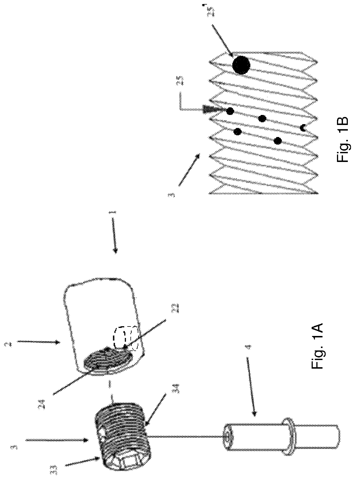
[0063]The mounting unit 1 of the invention provide a high degree of flexibility in conjunction with the first embodiment and other embodiments of the invention, in particular as follows:[0064]By varying the screw penetration depth of the drum assembly 3 inside the drum receiving unit 2 the position of an add-on piece connected to the bolt 4 within the boundaries of the aperture 22 can be adjusted.[0065]By varying the screw penetration depth of the bolt 4 inside the drum assembly 3 the distance of an add-on piece with respect to the drum receiving unit 2 can be adjusted.[0066]By having a specifically designed bolt 4, in particular by an angled bolt, the angle, position and / or orientation of an add-on piece can be adjusted during a 360° rotation of the bolt 4.

[0067]In the following different embodiments of the drum receiving unit 2, 2a, 2b, 2c, and 2d; the drum assembly 3, 3a, 3b, 3c, and 3d; and the bolt 4, 4a, and 4b are described individually. It is to be understood that they all m...

second embodiment

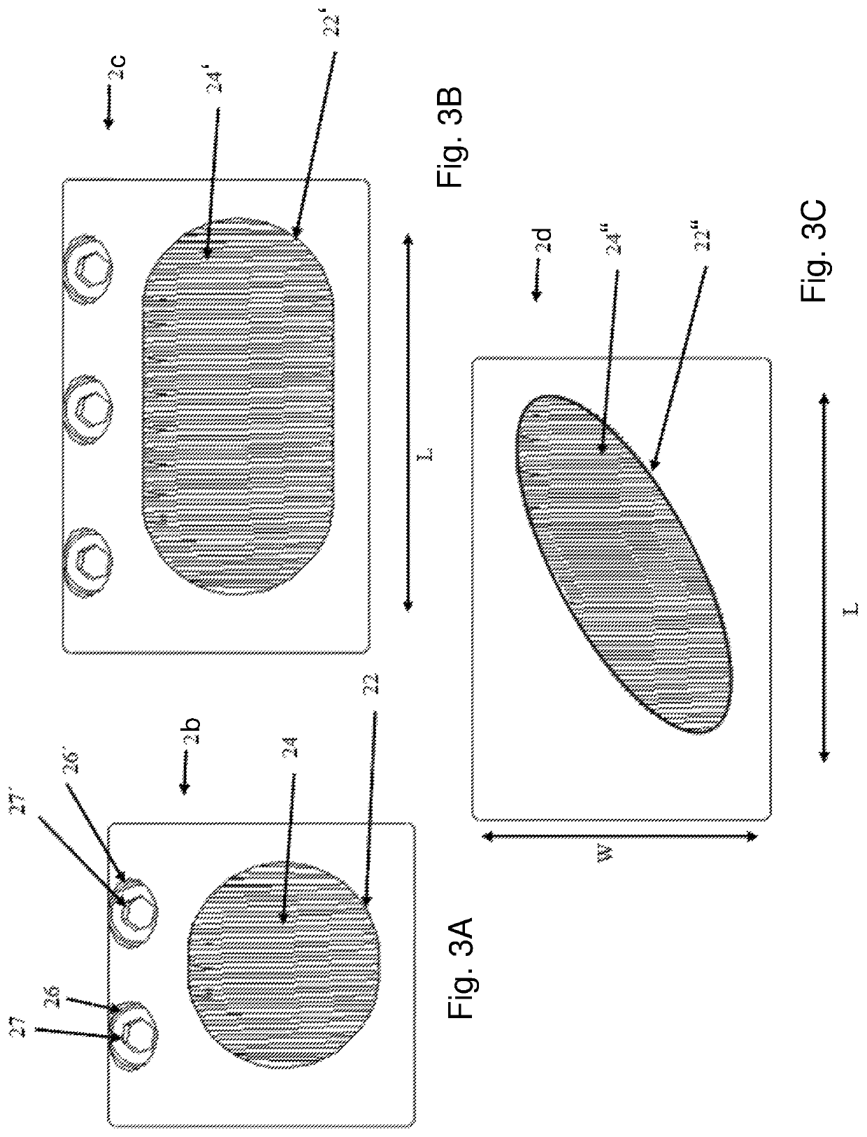
[0069]a drum receiving unit 2a is shown in FIG. 2a. Here the drum receiving unit 2a comprises, in addition to the aperture 22 and the female thread 24, a slit 23 and a socket 26. The socket 26 comprises a first connection portion 28 and opposing the first connection portion 28, on the other side of the slit 23, a corresponding second connection portion (not shown). The corresponding connection portions 28 of the socket 26 are configured to be brought in operative connection with a fastening means 27 such as a screw or a strap. The fastening means 27 can be used to reduce and / or close the slit 23 and realize a force fitting connection, especially between the drum receiving unit 2a and the drum assembly 3. In another embodiment shown in FIG. 2B, a drum receiving unit 2b, similar to the drum receiving unit 2a, comprises more than one socket 26 for closing the slit. This ensures that enough force can be applied and that the force can be distributed equally and / or specifically at certain...

fifth embodiment

[0080]In FIG. 8D, a drum assembly 3c of a fifth embodiment is shown. The drum assembly 3c has here a larger size along the cylinder axis to provide more than one hole 34, in particular a separate second hole 34′ also having a female thread 36′. Here the hole 34′ is rotated with respect to hole 34 by 90°, however, any other angle is also possible. Having a separate second hole allows either the usage of a second bolt 4, inserted at a different position and / or angle, or varying the position and / or angle of a single bolt 4. In another not shown embodiment, the second hole 34′ has an angle of 90° with respect to and has at least partly an overlap with the first hole 34. Therefore the step size for the bolt position adjustment can be partly reduced. When using an embodiment having two holes with two counterbores each, the step size for the adjustment of the bolt 4 can be made to equal approximately a quarter turn of the drum assembly 3.

[0081]The individual features of these four embodime...


PUM


Abstract

A mounting unit for adjustably mounting an add-on piece to a frame, in particular of a wheelchair, includes at least one drum receiving unit having at least one aperture and female thread. The drum receiving unit is an integral part of the frame or adapted to be attached to the frame. At least one drum assembly has at least one hole and a male thread. At least one bolt is part of the add-on piece or adapted to be mounted therewith to hold the add-on piece. The drum receiving unit is adapted to receive the drum assembly. The female thread mates with the male thread and allows an alignment of the position of the hole with respect to the aperture, such that the bolt can be inserted through the aperture at least partly into the hole. The drum receiving unit with the drum assembly and / or the drum assembly with the bolt comprises a detachable form fit connection. At least one of the drum receiving unit, the drum assembly and / or the bolt comprises a detachable force fit connection with respective mating component.

Description

CROSS-REFERENCE TO RELATED APPLICATIONS[0001]This application claims priority from German Patent Application No. 102018117476.4, filed on Jul. 19, 2018, the disclosure of which is incorporated herein by reference in its entirety.BACKGROUND OF THE INVENTION[0002]This invention relates in general to a mounting unit, especially a mounting unit for a wheelchair frame, a caster wheel assembly comprising such a mounting unit and a wheelchair with such a caster wheel assembly and / or such a mounting unit. In particular the invention relates to a mounting unit for adjustably mounting an add-on piece to a frame, in particular of a wheelchair.[0003]Previously, either form-fitting elements such as gears or bolts in hole patterns were employed for highly loaded and angle-adjustable attachments or continuously adjustable cylindrical clamped connections for less demanding loads. Whereas clamped connections may lack resilience and durability, form fitting connections are often too heavy and bulky. ...

Claims


Application Information

Patent Timeline
Patent Type & Authority Patents(United States)
IPC IPC(8): A61G5/10B60B33/00B60B33/04
CPCA61G5/10B60B33/0005B60B33/04A61G5/1097A61G5/1083
Inventor KNOPF, MICHAEL
Owner SUNRISE MEDICAL (US) LLC
Learn More