
Magnetically connectable grip and connector for electronics

a technology of magnetic connection and electronics, applied in the direction of electrical equipment, substation equipment, telephone set construction, etc., can solve the problems of increased size, increased size, and increased size of users' hands, so as to improve wireless charging, reduce magnetic interference, and enhance magnetic strength

Active Publication Date: 2022-05-10
OHSNAP INC
View PDF6 Cites 2 Cited by
  • Summary
  • Abstract
  • Description
  • Claims
  • Application Information

AI Technical Summary

Benefits of technology

The invention is a wireless charging device that uses a special arrangement of magnets to enhance its magnetic strength and reduce magnetic interference. This arrangement consists of two rows of magnets: one with positive polarity and one with negative polarity. This multi-polarity arrangement focuses the magnetic fields and increases the magnetic strength, resulting in improved wireless charging performance.

Problems solved by technology

In recent years, these devices have increased in size, leaving users with smaller hands unable to adequately grasp their smartphone during use.
Even users with larger hand sizes may struggle to safely hold their smartphone while using the total functional area of the smartphone's touchscreen interface.
Many finger holders are unable to function as a smartphone stand, which may be used to hold upright or at an angle the smartphone on a surface such as a tabletop.
However, wireless charging systems in the current arts are unable to be used with conventional finger holders.

Method used


Image

  • Magnetically connectable grip and connector for electronics
  • Magnetically connectable grip and connector for electronics
  • Magnetically connectable grip and connector for electronics

Examples


Embodiment Construction

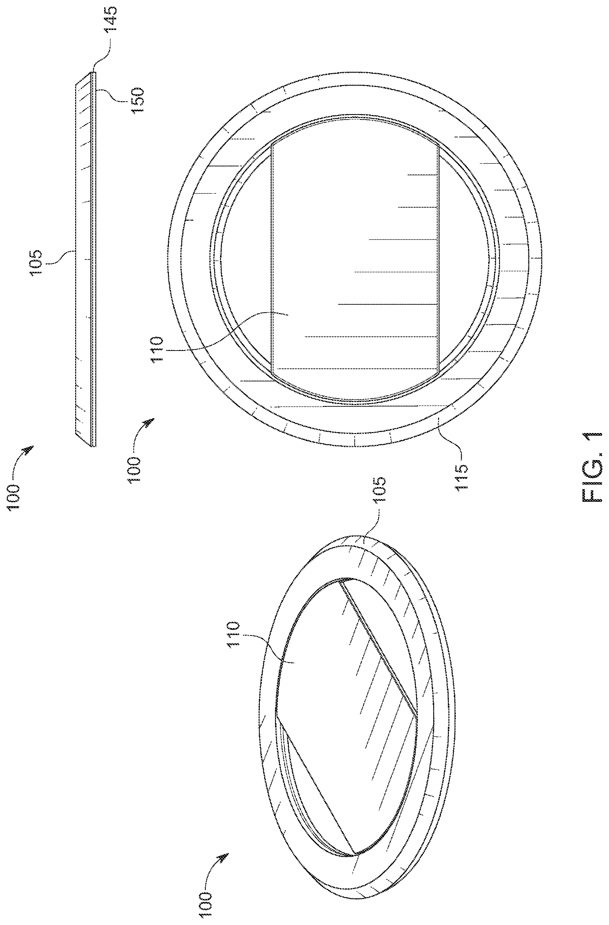
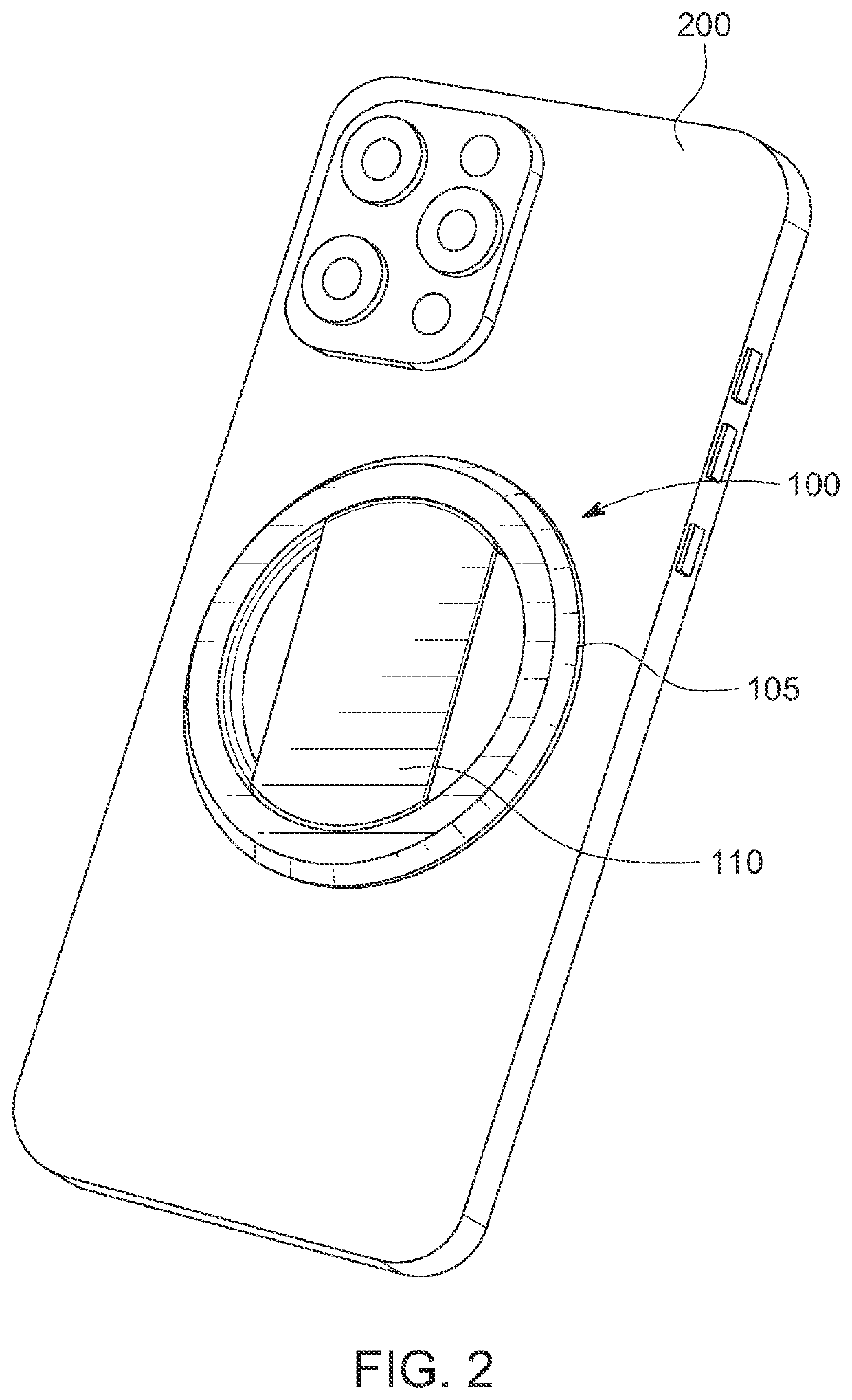
[0039]Embodiments of the invention disclosed herein relate to a finger grip for portable electronics, in particular a finger grip for cell phones. Referring to FIG. 1, a grip 100 is illustrated according to an example embodiment of the invention. The grip 100 includes a ferromagnetic steel, nickel plated ring 145 with double sided adhesive 150 on one side of the ring. The ring is adhered to the back of a cell phone 200 as shown in FIG. 2 or a case of a cell phone and provides the means for a grip assembly 105 to magnetically attach to the ring 145.

[0040]The finger grip 100 is comfortable and a quickly deployable finger grip 100. FIG. 3 illustrates the simplicity of installation of the deployable finger grip 100 on a cell phone 200. The finger grip 100 is provided in two parts, which may be assembled and shipped in a package, but separable by hand as shown on the left. Next, an adhesive covering is removed from a side of the metallic ring 145 and the metallic ring is adhered to the r...


PUM


Abstract

Finger grip and connector for portable electronics, in particular cell phones. The grip includes a metallic ring. The ring adheres to the back of a cell phone, or case. The grip includes a corresponding ring of magnets for a grip assembly to magnetically attach to the metal ring adhered to the cell phone. The grip design provides infinite rotation of the grip assembly relative to the phone for holding the phone in various positions. The grip provides a support for viewing content on the electronic device at different angles and orientations. The grip provides a means of magnetically attaching a cell phone to metallic surfaces, chargers, mounts, and other devices. The grip can allow for wireless charging, which is optimized and enabled by a relatively large open inner diameter of the metallic ring and corresponding magnets. The grip can retract to be less than 3 millimeters in total thickness.

Description

CROSS-REFERENCE TO RELATED APPLICATIONS[0001]This application is a continuation of International Application PCT / US2021 / 35514, with an international filing date of Jun. 2, 2021, which claims priority to and the benefit of U.S. Provisional Application No. 63 / 033,408, filed Jun. 2, 2020, the contents of both applications are incorporated herein by reference in their entirety and for all purposes.BACKGROUND OF THE INVENTION[0002]Smartphones have become seemingly ubiquitous in modern society. A smartphone is a portable device that combines mobile telephone and computing functions into one unit. They are distinguished from feature phones by their stronger hardware capabilities and extensive mobile operating systems, which facilitate wider software, internet (including web browsing over mobile broadband), and multimedia functionality (including music, video, cameras, and gaming), alongside core phone functions such as voice calls and text messaging. Smart phones generally have a touch scr...

Claims


Application Information

Patent Timeline
Patent Type & Authority Patents(United States)
IPC IPC(8): H04M1/00H04M1/02
CPCH04M1/0281H04M1/04H04B2001/3861H04B1/385H04B1/3883H04B1/3877H02J50/70
Inventor BACKUS, DALE
Owner OHSNAP INC
Learn More