
Display device including a light shielding layer covering a gap

a technology of light shielding layer and display device, which is applied in the field of display devices, can solve the problems of light leakage from the edge of the display device, peeling of the display panel and the backlight module, and the structure of the conventional module design in the market is limited, so as to reduce the thickness of the plastic frame or sheet metal, the basic structure of the display device is stable, and the frame of the module is reduced

Active Publication Date: 2022-05-10
WUHAN CHINA STAR OPTOELECTRONICS TECH CO LTD
View PDF8 Cites 0 Cited by
  • Summary
  • Abstract
  • Description
  • Claims
  • Application Information

AI Technical Summary

Benefits of technology

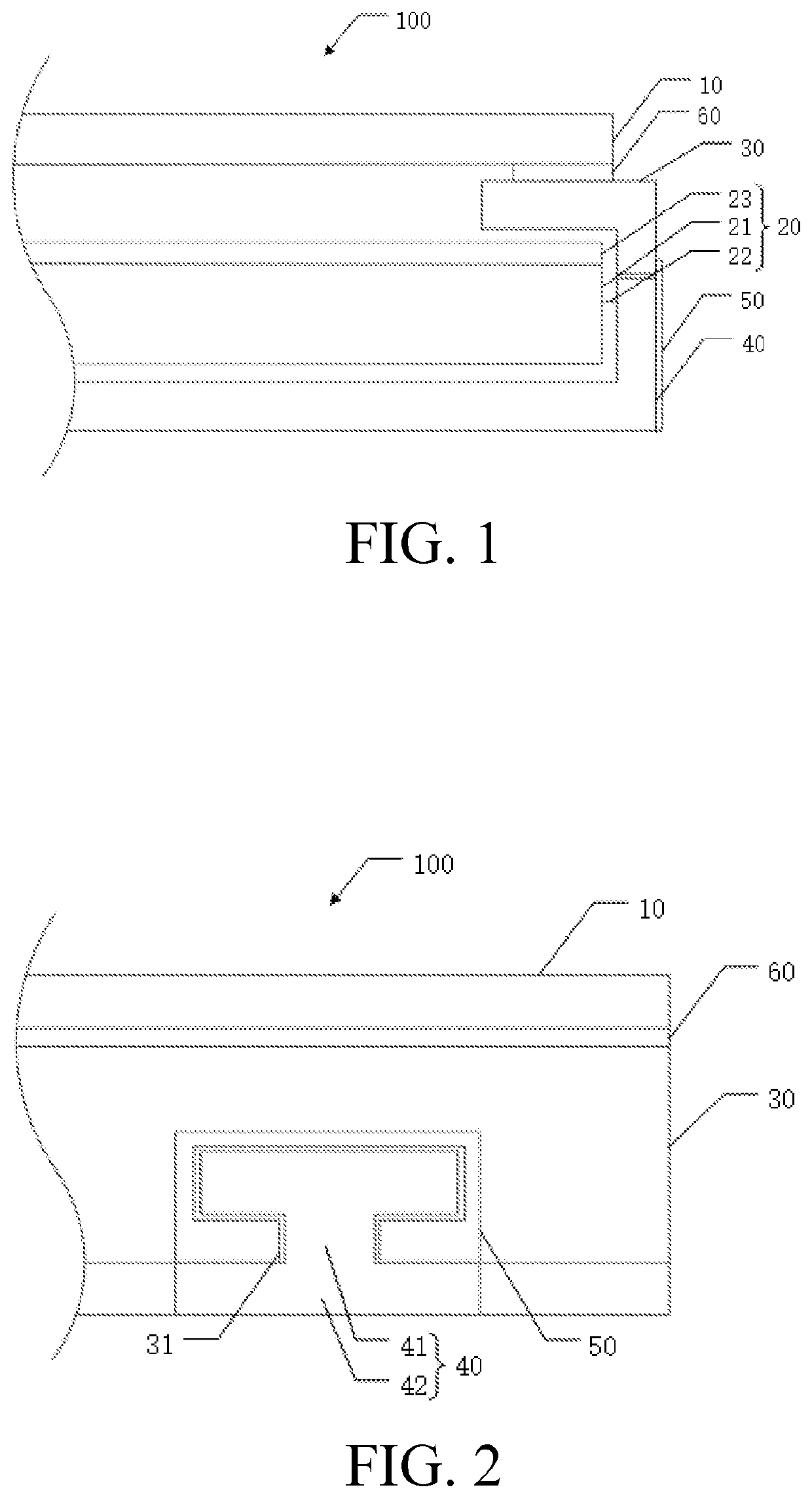
The present invention is a display device that fixes the plastic frame on the sheet metal by engaging the bent portion of the sheet metal with the slot of the middle frame, which ensures a stable basic structure of the display device. The plastic frame does not increase in thickness while its structural function is realized, reducing the frame of the module compared to the current design. Additionally, the problem of light leakage from an edge in the prior art is solved by providing the light shielding layer.

Problems solved by technology

However, borderless displays on the market are not really completely borderless.
Since the reliability requirements of in-vehicle display devices are relatively strict, the conventional module design in the market is limited by their structures.
Narrow border or borderless design may cause problems such as light leakage from an edge of the display device and peeling of the display panel and the backlight module after the reliability test.

Method used


Image

  • Display device including a light shielding layer covering a gap

Examples


Embodiment Construction

[0020]The embodiments of the present application are described in detail below, and the examples of the embodiments are illustrated in the drawings, wherein the same or similar reference numerals are used to refer to the same or similar elements or elements having the same or similar functions. The embodiments described below with reference to the accompanying drawings are intended to be illustrative and are not to be construed as limiting.

[0021]In the description of the present application, it is to be understood that the term “center”, “longitudinal”, “transverse”, “length”, “width”, “thickness”, “upper”, “lower”, “front”, “back”, “left”, “right”, “vertical”, “horizontal”, “top”, “bottom”, “inside”, “outside”, “clockwise”, “counterclockwise”, etc. is based on orientation or positional relationship shown in the drawings, and is merely for the convenience of describing the present application and the simplified description, and does not indicate or imply that the device or element r...


PUM

PropertyMeasurementUnit
shapeaaaaaaaaaa
thicknessaaaaaaaaaa
distanceaaaaaaaaaa

Abstract

The invention provides a display device, including a backlight module, a plastic frame, and a sheet metal. The plastic frame is disposed on a side of the backlight module, and the plastic frame has a slot. The sheet metal includes a bottom portion and a bent portion perpendicular to the bottom portion, and the bent portion is bent to a side surface of the backlight module and correspondingly engaged in the slot of the plastic frame.

Description

FIELD OF INVENTION[0001]The present invention relates to the field of display, and particularly to a display device.BACKGROUND OF INVENTION[0002]With the development of display devices, people have increasingly higher demand on the appearance of display devices. Narrow border and borderless display devices are more attractive than wide border display devices and have better visual effects, consequently becoming the mainstream in current display devices. However, borderless displays on the market are not really completely borderless. They merely make the border of displays very small and narrow, so that the human eye cannot detect the border at a long distance, thereby achieving the effect of borderless.[0003]In the field of in-vehicle display devices, people also have increasingly higher demand on the appearance of in-vehicle display devices and narrower border of vehicle display modules. At present, in-vehicle display devices usually adopt a design in which a middle plastic frame o...

Claims


Application Information

Patent Timeline
Patent Type & Authority Patents(United States)
IPC IPC(8): G02F1/1333F21V8/00
CPCG02F1/133317G02B6/0088G02F1/1339G02F1/133308G02F1/133512G02F1/133314G02F1/133608
Inventor ZHOU, ZHENG
Owner WUHAN CHINA STAR OPTOELECTRONICS TECH CO LTD
Learn More