
Particle or pollen sensor and sensing method

a technology of particle or pollen and sensor, applied in the direction of suspensions and porous materials, material analysis, instruments, etc., can solve the problems of high cost of sensor, general only used in professional applications, and unknown optical based sensors that generally do not take into account, and achieve the effect of effective cleaning mechanism

Active Publication Date: 2022-05-10
KONINKLJIJKE PHILIPS NV
View PDF7 Cites 0 Cited by
  • Summary
  • Abstract
  • Description
  • Claims
  • Application Information

AI Technical Summary

Benefits of technology

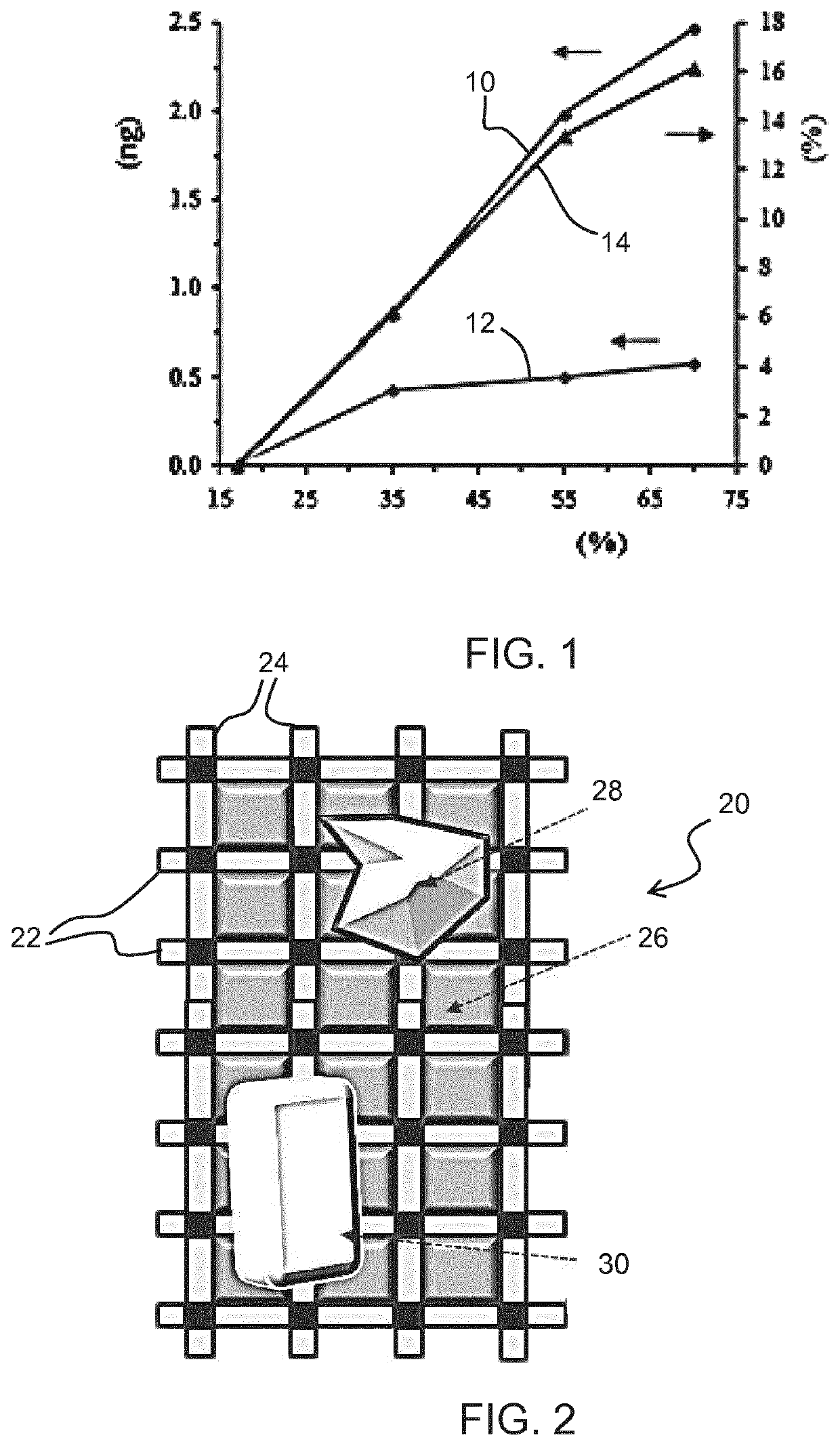
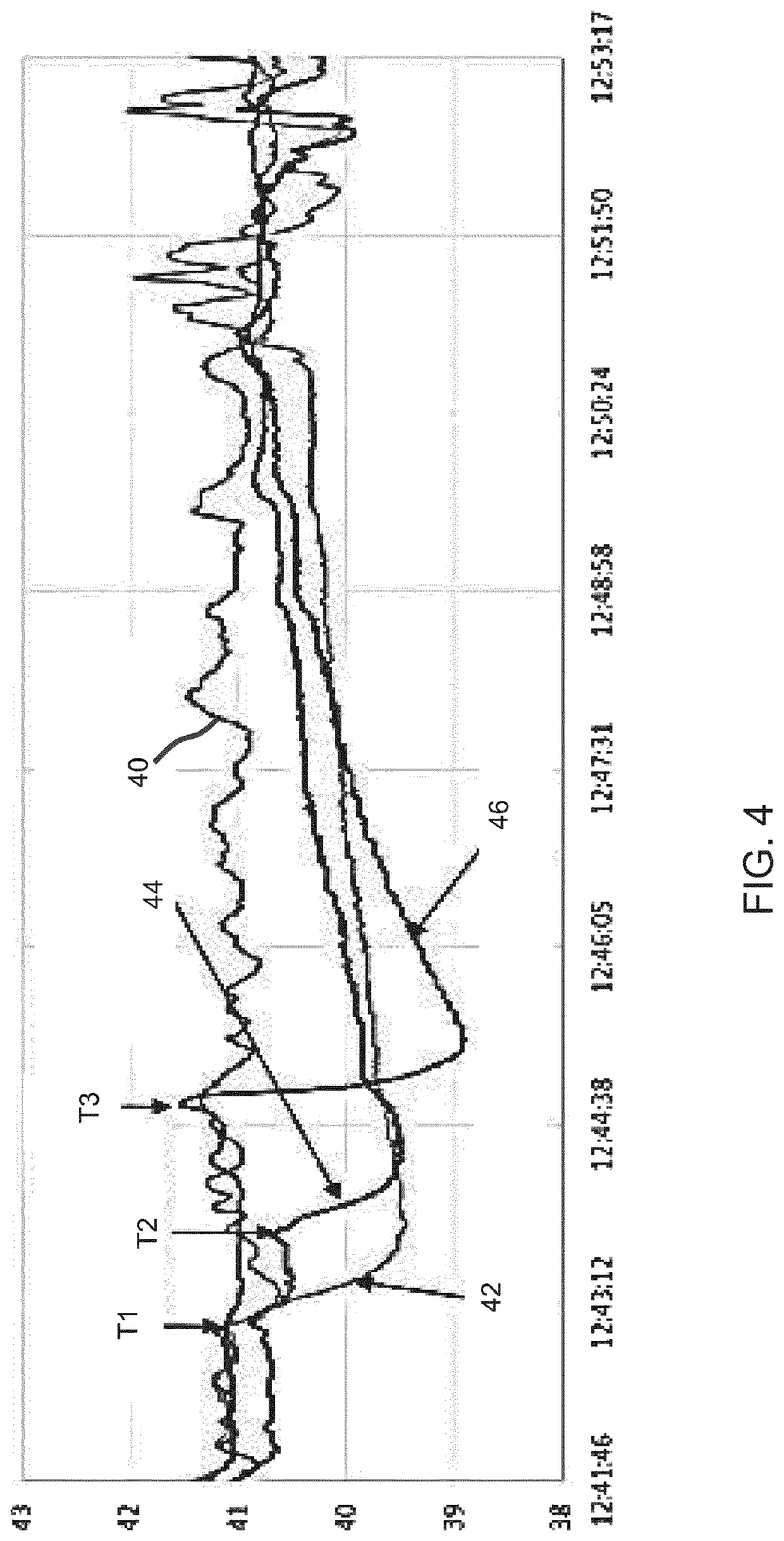
[0019]The invention provides a particle or pollen sensor in which different particle types such as pollen are detected based on their difference in hygroscopicity, which in turn depends on the surface structure and dry mass. The invention is based on distinguishing the hygroscopicity or water content of pollen or other particles by making use of relative humidity sensors, and this enables a low cost and small pollen sensor to be formed. For the detection of pollen, the sensor may be used to identify the presence of any pollen based on the general property of taking up water, or it may additionally be used to distinguish between pollen types for example by performing a size analysis as well.
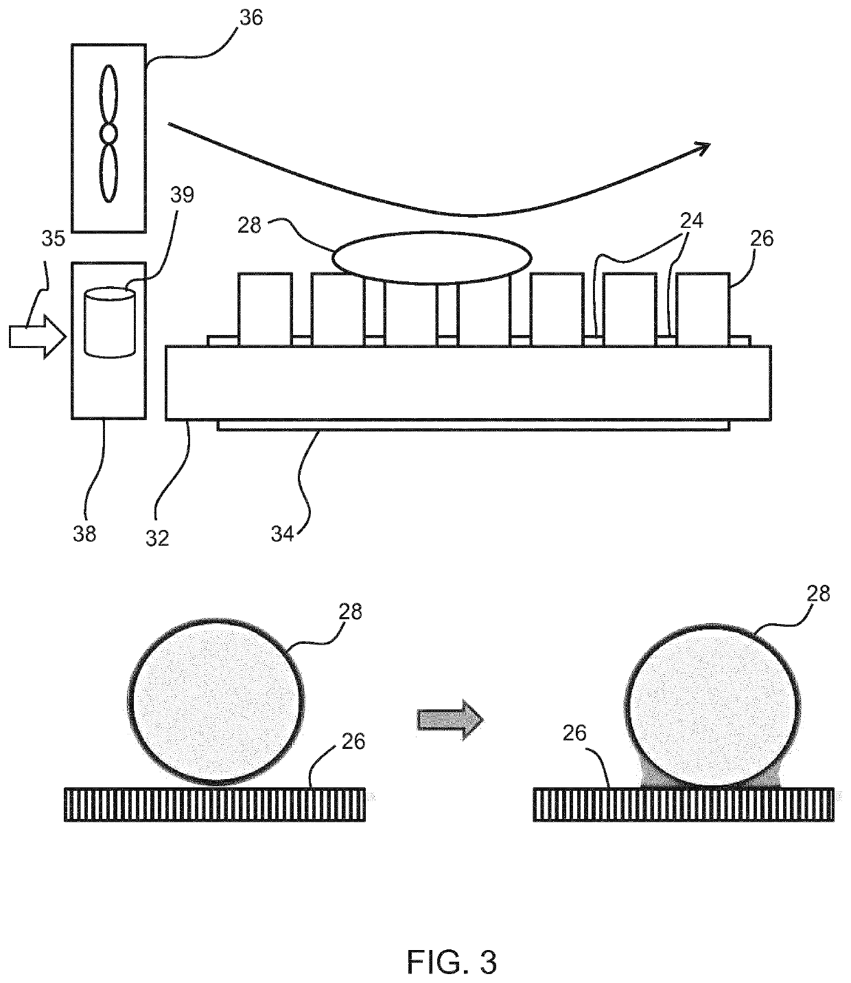
[0027]The sensor preferably further comprises a vibrator for dislodging particles or pollen from the array of relative humidity sensors. The combined effect of vibration and an air flow provides an effective cleaning mechanism.
[0028]The vibrator for example comprises a piezoelectric vibrator attached to the array of relative humidity sensors. It may for example be coupled to a substrate of the sensor array. The array of relative humidity sensors for example comprises an array of polymer elements and an array of readout conductors, and a detection circuit for monitoring impedance values associated with each polymer element. The impedance varies with the take up of moisture transferred from the particle or pollen, and this enables measurement of the water take up of the particle or pollen.

Problems solved by technology

Furthermore, sensors for accurately determining size distribution information are expensive and generally only used in professional applications.
However, these known optical based sensors generally do not take into account a number factors which introduce inaccuracies.
The size of pollen also changes with humidity due to hygroscopicity.

Method used


Image

  • Particle or pollen sensor and sensing method
  • Particle or pollen sensor and sensing method
  • Particle or pollen sensor and sensing method

Examples


Embodiment Construction

[0049]The invention provides a particle or pollen sensor which comprises an array of relative humidity sensors. A change in relative humidity is representative of a particle or pollen in contact with one or more of the sensors. Thus, detecting a change of relative humidity in relative humidity measurement wherein the change in relative humidity is representative of a particle or pollen. A size and / or shape of a particle or pollen in contact with one or more of the sensors is optionally also determined based on the number and / or configuration of sensors. From this information, a particle or pollen is determined and optionally also a particle type or pollen type.

[0050]The invention is based on the recognition that pollen and some other particle types may be detected based on different water uptake characteristics.

[0051]The invention will be described with reference to a pollen sensor. However, as will be clear from the description below, the size determination aspect may be used to id...


PUM

PropertyMeasurementUnit
areaaaaaaaaaaa
diameteraaaaaaaaaa
sizeaaaaaaaaaa

Abstract

A particle or pollen sensor comprises an array of relative humidity sensors. A change in relative humidity is representative of a particle or pollen in contact with one or more of the sensors. A size and / or shape of a particle or pollen in contact with one or more of the sensors is optionally also determined based on the number and / or configuration of sensors. From this information, a particle or pollen type is determined.

Description

CROSS REFERENCE TO RELATED APPLICATIONS[0001]This application is the U.S. National Phase application under 35 U.S.C. § 371 of International Application No. PCT / EP2018 / 077236 filed Oct. 8, 2018, published as WO 2019 / 072722 on Apr. 18, 2019, which claims the benefit of European Patent Application Number 17199742.2 filed Nov. 2, 2017 and Patent Application Number PCT / CN2017 / 105407 filed Oct. 9, 2017. These applications are hereby incorporated by reference herein.FIELD OF THE INVENTION[0002]This invention relates to a method and apparatus for sensing and identifying particles or pollen.BACKGROUND OF THE INVENTION[0003]It is well known that it is desirable to monitor pollution levels, such as particulate pollutants including pollen. Various sensing devices are known, which for example provide a particle concentration level for particles below a certain size, over a certain size, or within a size range. Optical particle sensing approaches are for example known based on optical scattering....

Claims


Application Information

Patent Timeline
Patent Type & Authority Patents(United States)
IPC IPC(8): G01N15/10G01N15/02
CPCG01N15/10G01N15/02G01N2015/0046G01N15/0606G01N15/00G01N15/06
Inventor ZHANG, PENGCHEN, SHUANGZHANG, QIUSHI
Owner KONINKLJIJKE PHILIPS NV
Learn More