
Electromagnetic and triboelectric hybrid energy collector for low-frequency movement

a hybrid energy collector and triboelectric technology, applied in the field of energy collection technologies, can solve the problems of limited service life, large amount of vibration energy stored, environmental pollution, etc., and achieve the effect of superior hybrid power system overall performan

Active Publication Date: 2022-04-19
SHANGHAI UNIV
View PDF53 Cites 16 Cited by
  • Summary
  • Abstract
  • Description
  • Claims
  • Application Information

AI Technical Summary

Benefits of technology

The patent describes a device that collects energy from low-frequency movement, such as human movement. It combines two types of energy collection technologies: electromagnetic and triboelectric. This results in a low resonance frequency, allowing for energy collection at a low vibration frequency. The device also has superior performance compared to separate electromagnetic and triboelectric power systems.

Problems solved by technology

However, traditional energy sources such as petroleum, coal and various chemical batteries have many inherent disadvantages, such as environmental pollution and limited service life.
And a large amount of vibration energy is stored in them for collection.
However, the target working interval of most existing energy collectors is a medium-high frequency interval from tens of hertz to hundreds of hertz, and energy collection of low-frequency vibration is rarely researched.
However, the nano-friction generator is high in output voltage, small in output current and not easy to integrate.
However, the electromagnetic energy collector is large in output current and high in output power.
It can be seen that the design and development of, an electromagnetic and triboelectric hybrid energy collector is a problem that urgently needs to be solved at present.

Method used


Image

  • Electromagnetic and triboelectric hybrid energy collector for low-frequency movement
  • Electromagnetic and triboelectric hybrid energy collector for low-frequency movement
  • Electromagnetic and triboelectric hybrid energy collector for low-frequency movement

Examples


Embodiment Construction

[0032]The following clearly and completely describes the technical solution in the embodiments of the present disclosure with reference to the drawings in the embodiments of the present disclosure. Apparently, the described embodiments are merely a part rather than all of the embodiments of the present disclosure. Based on the embodiment in the present disclosure, all other embodiments obtained by the ordinary technical staff in the art under the premise of without contributing creative labor belong to the scope protected by the present disclosure.

[0033]The embodiment aims to provide an electromagnetic and triboelectric hybrid energy collector for low-frequency movement to solve the problems existing in the prior art.

[0034]To make the foregoing objective, features and advantages of the present disclosure clearer and more comprehensible, the present disclosure is further described in detail below with reference to the drawings and the specific embodiment.

[0035]The electromagnetic and...


PUM


Abstract

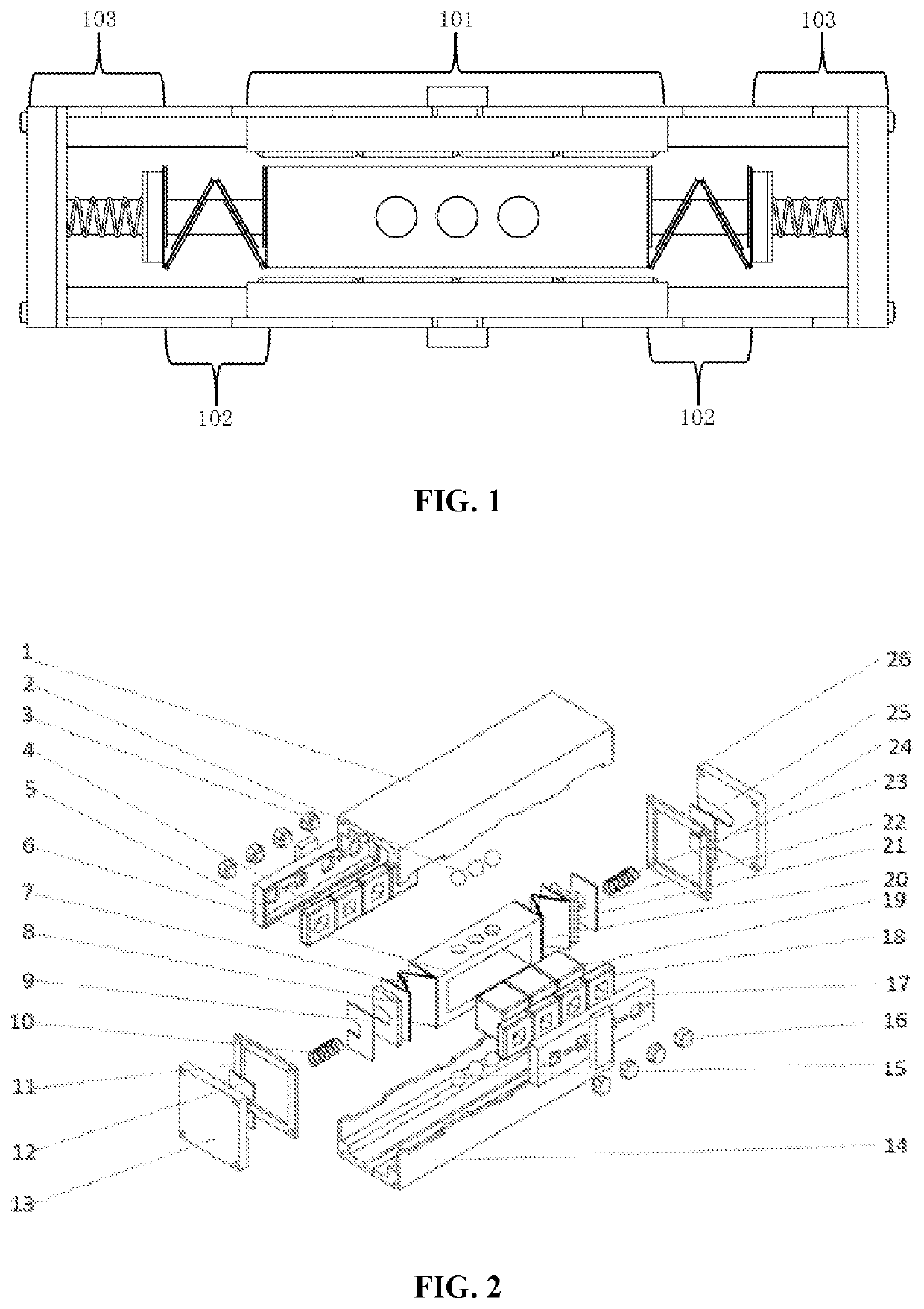
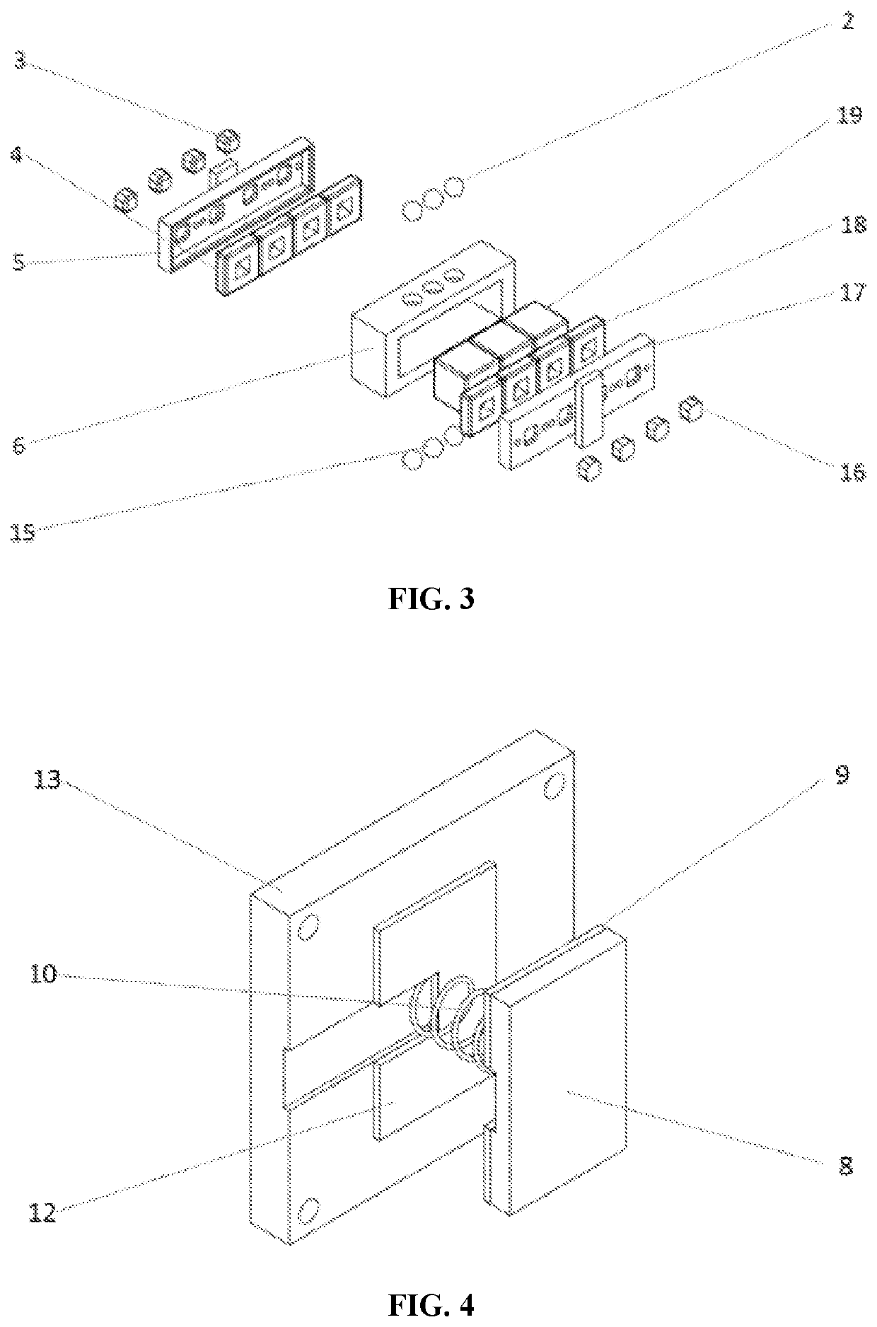
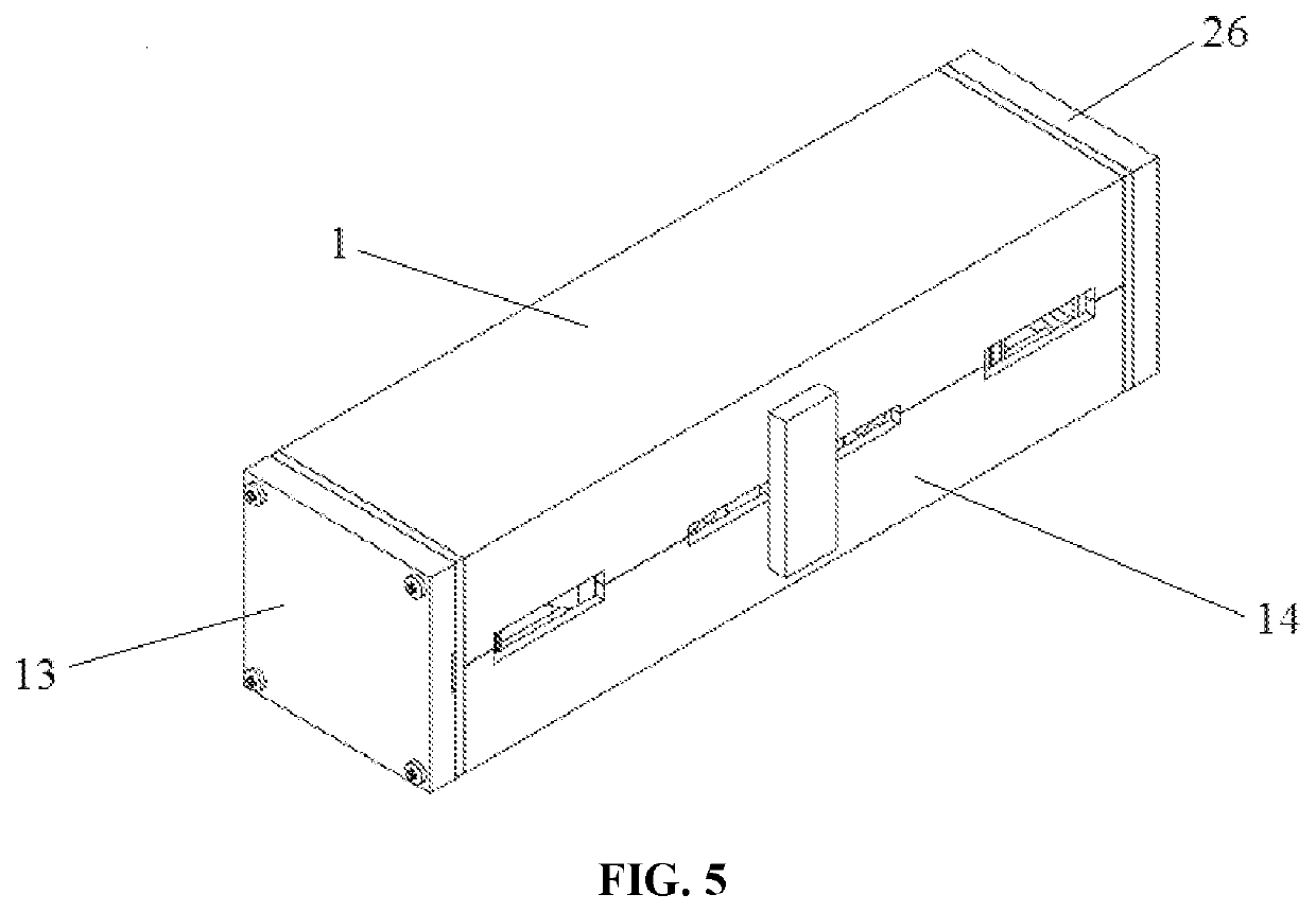
An electromagnetic and triboelectric hybrid energy collector for low-frequency movement is provided. The electromagnetic and triboelectric hybrid energy collector comprises an electromagnetic module, triboelectric modules and spring mass modules. The electromagnetic module includes a shell, a magnet frame, a magnet array, coil arrays, coil frames and coil magnetic conductive columns. The spring mass modules include respective springs, respective mass blocks and respective end caps. The triboelectric modules include multiple nano-friction power generation units which are connected in sequence. When the energy collector is excited to move a magnet assembly. The electromagnetic module generates voltage according to the Faraday's law of electromagnetic induction. The movement of the magnet assembly generated by external excitation may also cause contact and separation between triboelectric units to generate voltage.

Description

CROSS REFERENCE TO RELATED APPLICATION[0001]This patent application claims the benefit and priority of Chinese Patent Application No. 202011448823.2, entitled “Electromagnetic and Triboelectric Hybrid Energy Collector for Low-frequency Movement” filed on Dec. 9, 2020, the disclosure of which is incorporated by reference herein in its entirety as part of the present application.TECHNICAL FIELD[0002]The present disclosure relates to the field of energy collection technologies, and particularly relates to an electromagnetic and triboelectric hybrid energy collector for low-frequency movement.BACKGROUND ART[0003]In recent years, the demands of humans for energy and energy consumption are increasing. However, traditional energy sources such as petroleum, coal and various chemical batteries have many inherent disadvantages, such as environmental pollution and limited service life. In order to remedy these drawbacks, the collection of energy, such as solar energy, wind energy and tidal ene...

Claims


Application Information

Patent Timeline
IPC IPC(8): H02N1/04H02K35/02
CPCH02N1/04H02K35/02
Inventor LI, ZHONGJIEPENG, XUZHANGPENG, YANLUO, JUNXIE, SHAORONGPU, HUAYAN
Owner SHANGHAI UNIV
Learn More