
Washing machine

a washing machine and drum technology, applied in the field of washing machines, can solve the problems of waste of water resources, large capacity of washing machines, and gradual increase in capacity of washing machines, and achieve the effects of improving water-saving effect and dehydration efficiency, reducing water consumption, and prolonging service li

Active Publication Date: 2022-03-29
QINGDAO HAIER WASHING MASCH CO LTD +1
View PDF21 Cites 0 Cited by
  • Summary
  • Abstract
  • Description
  • Claims
  • Application Information

AI Technical Summary

Benefits of technology

The present invention provides a washing machine with a bigger washing drum, improved water-saving effect and dehydration efficiency, as well as a long service life. The washing drum is directly taken as a water holding drum, omitting the outer drum structure and allowing for a bigger size and increased capacity of the washing machine. The water drainage channel is arranged on the inner side of the washing drum to reduce noise and improve service life during dehydation. The invention also provides a locking mechanism at the bottom of the washing drum to limit rotation when a water drainage outlet is closed by a valve plug.

Problems solved by technology

Along with constant development of techniques of a washing machine, the capacity of a washing machine gradually tends to become bigger and bigger.
Meanwhile, for the existing washing machine, during clothes washing, water is distributed in a rotating drum and a water holding drum, that is, water is also distributed between the water holding drum and the rotating drum, therefore, water consumption is large, and water resources are wasted; for the existing washing machine, dirt easily remains between the water holding drum and a rotating drum, thereby breeding bacteria, moreover, since water is distributed between a water holding drum and a rotating drum, the consumption of detergent is also large, thereby leading to a waste of detergent resources and being not beneficial for saving cost.
In the patent, although an outer drum is omitted, however, the water collecting opening and the water drainage pipe are both arranged outside a drum, during dehydration of a washing machine, an inner wall of a cabinet is easily collided, thereby leading to abrasion of the water collecting opening and the water drainage pipe and leading to water leakage, and shortening service life of a washing machine.

Method used


Image

  • Washing machine
  • Washing machine
  • Washing machine

Examples


embodiment 1

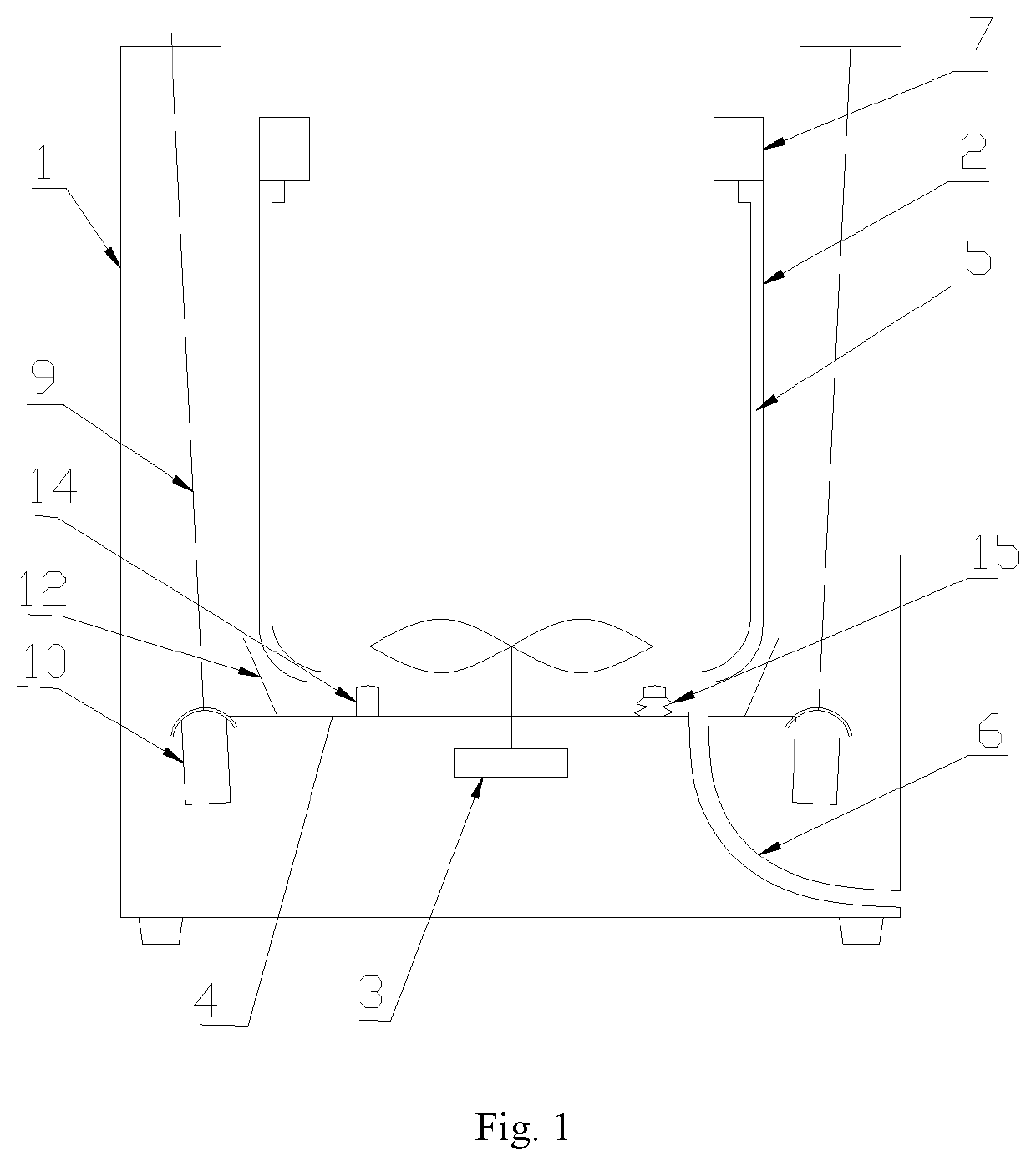
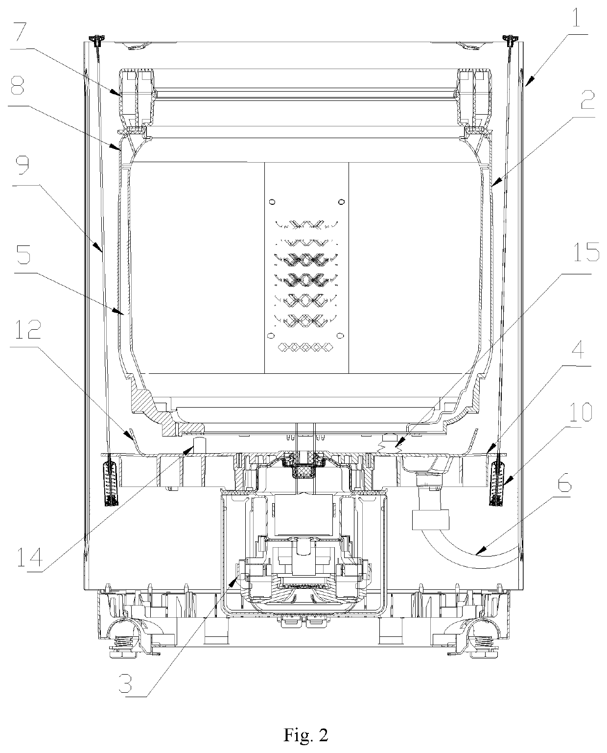
[0057]As shown in FIG. 1 and FIG. 2, the washing machine of the present embodiment includes a cabinet 1, a washing drum 2 configured to accommodate to-be-washed clothes, a power device 3 driving rotation of a washing drum 2 and a mounting plate 4 installed at a lower part of a washing drum 2, and a damping piece connecting a mounting plate 4 and a cabinet 1. The washing drum 2 can be rotatably arranged in the cabinet 1, the washing drum 2 is located on a mounting plate 4, and can rotate relative to the mounting plate 4, the washing drum 2 is taken as a water holding drum to accommodate washing water, the mounting plate 4 is configured to support a washing drum 2, and the mounting plate 4 is movably connected with a cabinet 1 through a damping piece, during washing or dehydration, the washing drum 2 and the mounting plate 4 will vibrate, and the vibration is transmitted to a damping piece and is absorbed.

[0058]A balancing ring 7 is arranged on a top end of the washing drum 2, a lower...

embodiment 2

[0059]A lower end of the water drainage channel 5 of the present embodiment is connected with a water drainage outlet at a bottom part of a washing drum 2 (not shown in the figures), the water drainage outlet is arranged below an impeller of a washing machine, the water drainage channel 5 extends to the water drainage outlet, as shown in FIG. 4 and FIG. 5, the water drainage channel 5 includes a water channel casing 11 and part of a washing drum wall, a side, facing a washing drum wall, of the water channel casing 11 is provided with a cut-through groove, the water channel casing 11 is fastened on the washing drum wall, and forms a water flow channel together with the washing drum wall. The water channel casing 11 is similar to a water channel structure in an inner drum of the existing washing machine, the difference is that an upper end of the water channel casing 11 extends until the water channel casing 11 is connected with a water collecting ring 8, and no water outlet is arrang...

embodiment 3

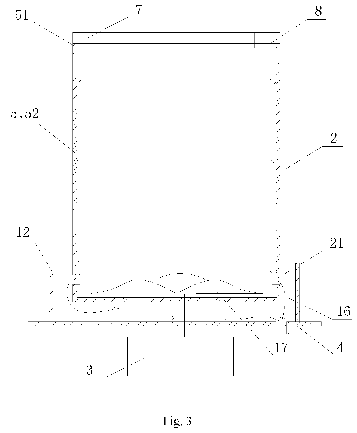
[0063]As shown in FIG. 3, a water retaining ring 12 is arranged on the mounting plate 4 in the present embodiment, the water retaining ring 12 protrudes towards a direction of a washing drum 2 from an upper surface of the mounting plate 4, and extends for a certain height, to form a concave cavity structure 16 which accommodates washing water, a bottom part of the concave cavity structure 16 is provided with an opening and is connected with a water drainage pipe 6, the water drainage pipe 6 is communicated with a water drainage outlet of a washing machine, preferably, the height of the water retaining ring 12 is slightly higher than a bottom surface of a washing drum 2, and a bigger gap is reserved between the water retaining ring 12 and an outer peripheral wall of the washing drum 2, to avoid collisions when a washing drum 2 rotates.

[0064]As shown in FIG. 1 and FIG. 2, a valve plug 15 is installed on a water drainage outlet at a bottom part of the washing drum 2, the valve plug 15 ...


PUM


Abstract

A washing machine comprises a cabinet, a washing drum rotatably arranged in the cabinet, wherein the washing drum is a water holding drum to accommodate washing water, a water drainage channel which discharges water from top to bottom is arranged at an inner side of a peripheral wall of the washing drum, an upper end of the water drainage channel communicates with the inside of a washing drum, and a lower end communicates with the outside of the washing drum. The water drainage channel comprises a water channel casing and at least part of a washing drum wall, and one side, facing the washing drum wall, of the water channel casing is provided with a cut-through groove, the water channel casing is fastened on the washing drum wall, and forms a water flow channel together with the washing drum wall.

Description

TECHNICAL FIELD[0001]The present disclosure relates to a clothes washing device, in particular to a washing machine.BACKGROUND ART[0002]An existing impeller-type washing machine generally includes a washing drum, an outer drum, a damping piece and a power system. During clothes washing and dehydration, a washing drum rotates relative to an outer drum, such that clothes and washing water produce an effect to achieve an object of washing clothes or dehydrating. Wherein an outer drum is taken as a water holding drum, in a process of washing clothes, the outer drum is not in contact with clothes, the outer drum is installed outside a washing drum, so as to provide support for the washing drum.[0003]Along with constant development of techniques of a washing machine, the capacity of a washing machine gradually tends to become bigger and bigger. While the gradually increased large capacity of a washing machine inevitably leads to an increase in an overall size of a washing machine, therefo...

Claims


Application Information

Patent Timeline
Patent Type & Authority Patents(United States)
IPC IPC(8): D06F39/08D06F23/04D06F37/24D06F37/12D06F37/20D06F37/30D06F39/10
CPCD06F39/083D06F23/04D06F37/12D06F37/206D06F39/08D06F37/24D06F37/30D06F39/081D06F39/10D06F37/145
Inventor LAO, CHUNFENGXU, SHENGLV, YANFENHAO, XINGHUILI, YIMINWU, DI
Owner QINGDAO HAIER WASHING MASCH CO LTD
Learn More