Magnetic tape recording and reproducing apparatus and recording and reproducing method
a technology of magnetic tape and recording apparatus, which is applied in the direction of recording on magnetic tape, maintaining head carrier alignment, instruments, etc., can solve the problems of not being able to prevent a and needing to proceed a complicated process, so as to prevent the decrease in the positioning accuracy of the magnetic head
- Summary
- Abstract
- Description
- Claims
- Application Information
AI Technical Summary
Benefits of technology
Problems solved by technology
Method used
Image
Examples
first embodiment
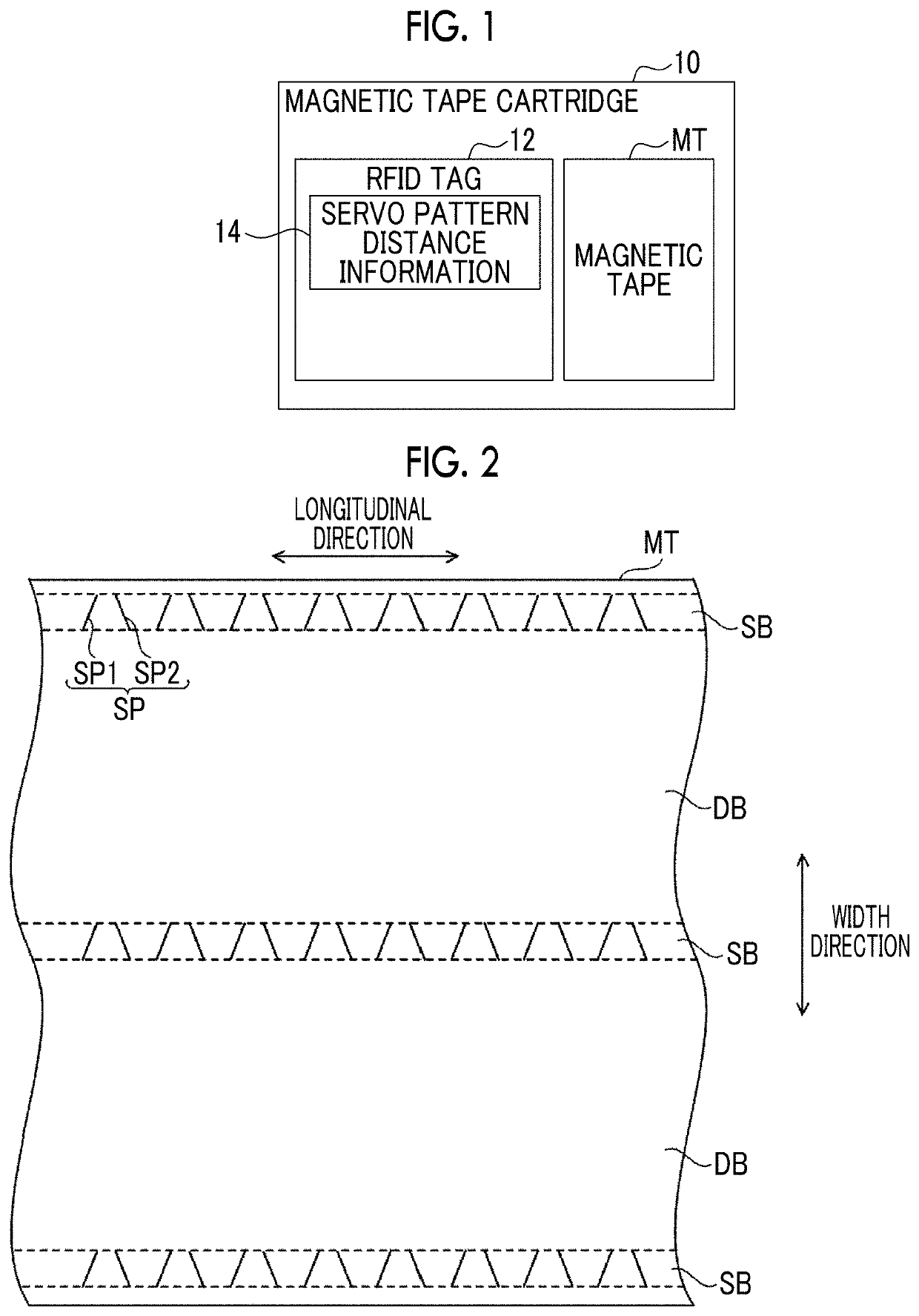
[0067]A configuration of a magnetic tape cartridge 10 according to the embodiment will be described with reference to FIGS. 1 and 2. As shown in FIG. 1, a magnetic tape cartridge 10 comprises a magnetic tape MT on which information is magnetically recorded, and a radio frequency identifier (RFID) tag 12 as an example of a second recording medium capable of recording and reading information by wireless communication or the like in a contactless manner. On the RFID tag 12, servo pattern distance information 14 and the like are recorded. Details of the servo pattern distance information 14 will be described later. An example of the magnetic tape MT is an LTO tape.
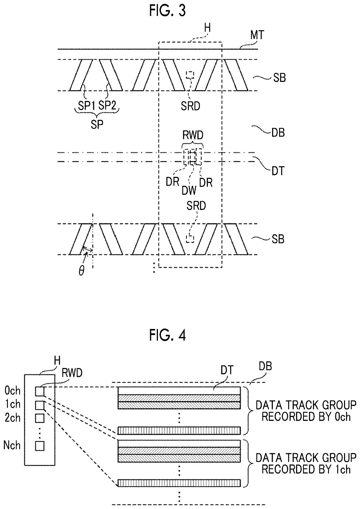
[0068]As shown in FIG. 2, three servo bands SB are formed on the magnetic tape MT along a longitudinal direction of the magnetic tape MT. The three servo bands SB are formed so as to be arranged in a width direction (short direction) of the magnetic tape MT at regular intervals. A data band DB, on which data is recorded, is fo...
second embodiment
[0112]A second embodiment of the technology of the disclosure will be described. The configuration of the recording and reproducing system 30 according to the embodiment is the same as that of the first embodiment except for the magnetic head H, and therefore the configuration of the magnetic head H will be described here.
[0113]The configuration of the magnetic head H according to the embodiment will be described with reference to FIG. 15. As shown in FIG. 15, the magnetic head H comprises a plurality of recording and reproducing elements RWD and four servo reproducing elements SRD. In the following description, in a case of distinguishing the four servo reproducing elements SRD, the numbers are added in order from the top to the end of the reference numerals, as a servo reproducing element SRD1 to a servo reproducing element SRD4.
[0114]The recording and reproducing element RWD is arranged along the tape width direction between a servo reproducing element SRD2 and a servo reproducin...
third embodiment
[0132]A third embodiment of the technology of the disclosure will be described. In the second embodiment, a case where a tension of the magnetic tape MT during the recording or reproducing of the data is set to a regulated tension has been described. In the embodiment, an example in which the tension of the magnetic tape MT during the recording or reproduction of the data is controlled in a different manner from the second embodiment will be described. The configuration of the recording and reproducing system 30 according to the embodiment is the same as that in the second embodiment, and therefore the description thereof will be omitted.
[0133]Next, a flow of a data recording process of recording data on the magnetic tape cartridge 10 performed by the recording and reproducing system 30 will be described with reference to FIG. 21. The data recording process shown in FIG. 21 is, for example, performed in a case where data which is a recording target is input to the controller 46 of t...
PUM
| Property | Measurement | Unit |
|---|---|---|
| width | aaaaa | aaaaa |
| width | aaaaa | aaaaa |
| width | aaaaa | aaaaa |
Abstract
Description
Claims
Application Information
 - R&D
- Intellectual Property
- Life Sciences
- Materials
- Tech Scout
- Unparalleled Data Quality
- Higher Quality Content
- 60% Fewer Hallucinations
Browse by: Latest US Patents, China's latest patents, Technical Efficacy Thesaurus, Application Domain, Technology Topic, Popular Technical Reports.
© 2025 PatSnap. All rights reserved.Legal|Privacy policy|Modern Slavery Act Transparency Statement|Sitemap|About US| Contact US: help@patsnap.com


