
Strength test method for metal roofing material, strength test equipment, and virtual strength test program

a technology of strength test and metal roofing, applied in the direction of material strength using steady bending force, instrumentation, design optimisation/simulation, etc., can solve the problem of relatively heavy over ceramic roofing material, and achieve the effect of more accurate and easy evaluation of the strength of metal roofing material

Active Publication Date: 2022-03-15
NISSHIN STEEL CO LTD
View PDF33 Cites 0 Cited by
  • Summary
  • Abstract
  • Description
  • Claims
  • Application Information

AI Technical Summary

Benefits of technology

Enables a more accurate and cost-effective evaluation of metal roofing material strength through a smaller-scale test, confirming the material's ability to withstand wind loads by determining the uplift coefficient, which indicates the material's resistance to wind speeds.

Problems solved by technology

On the other hand, the above ceramic roofing material has a problem that it is relatively heavy, for example.

Method used


Image

  • Strength test method for metal roofing material, strength test equipment, and virtual strength test program
  • Strength test method for metal roofing material, strength test equipment, and virtual strength test program
  • Strength test method for metal roofing material, strength test equipment, and virtual strength test program

Examples


embodiment 1

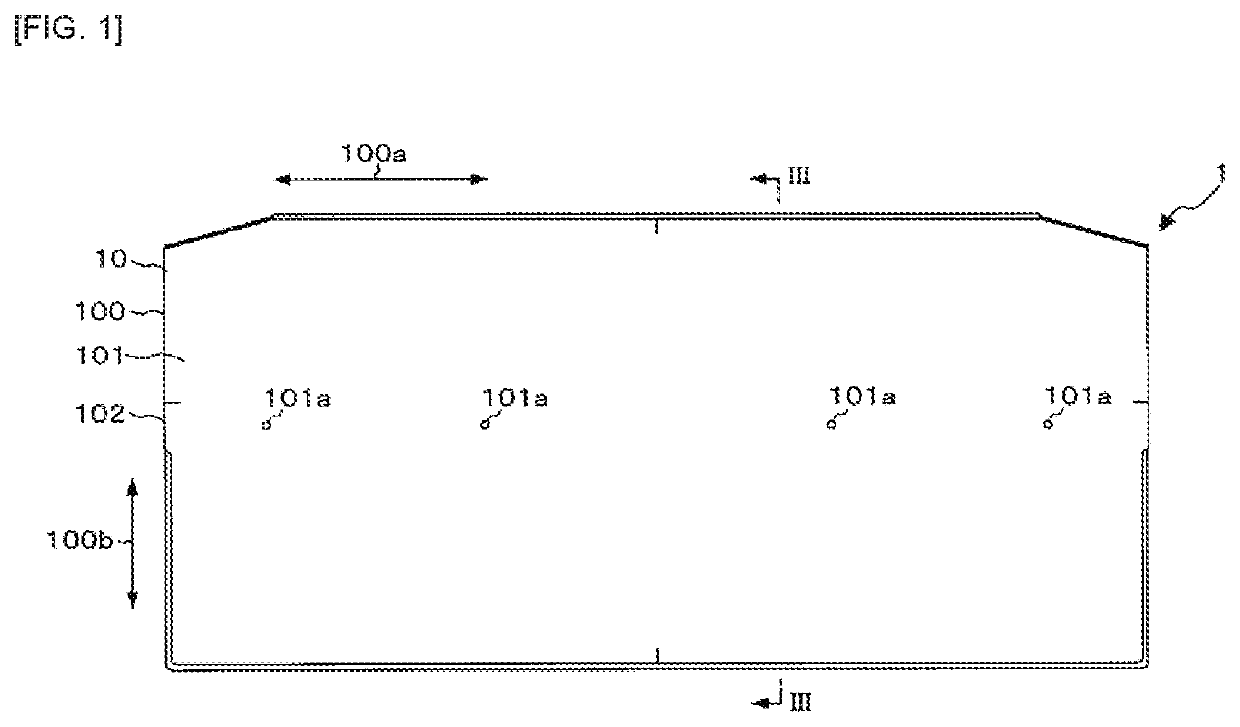
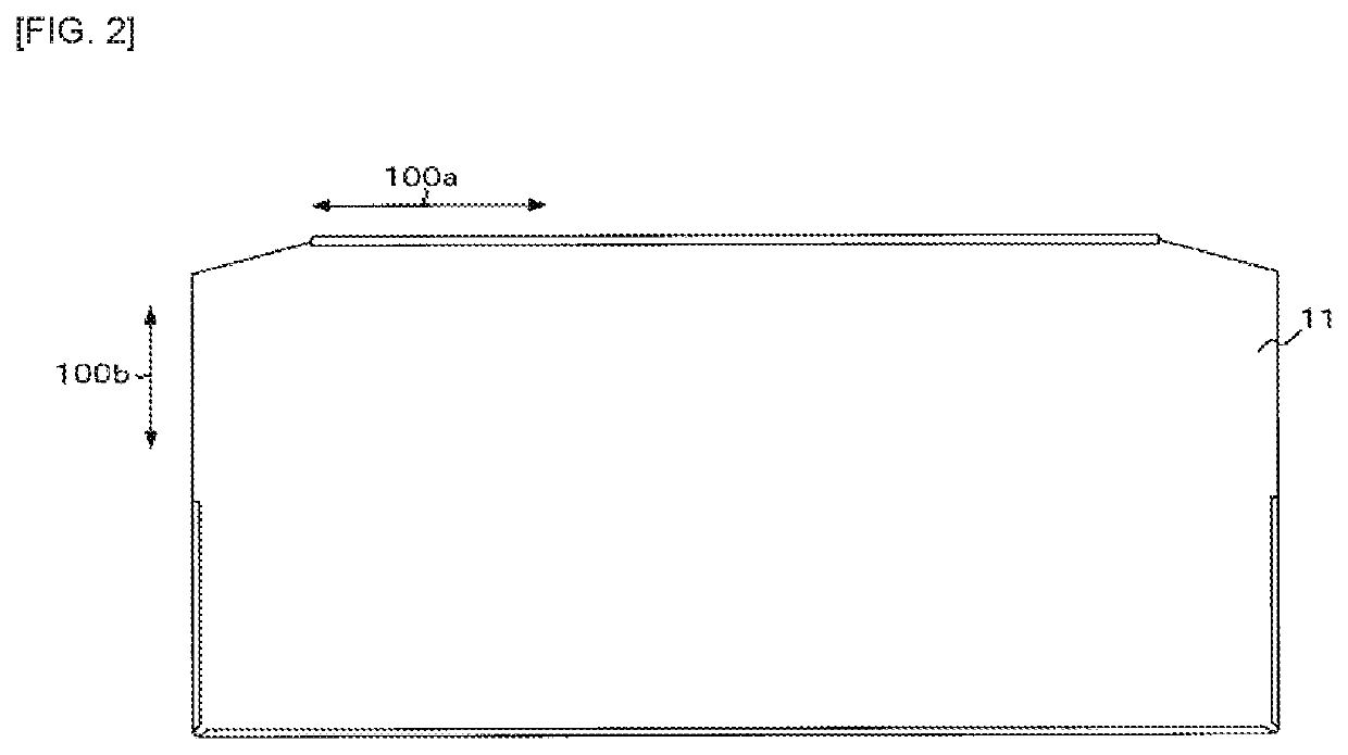
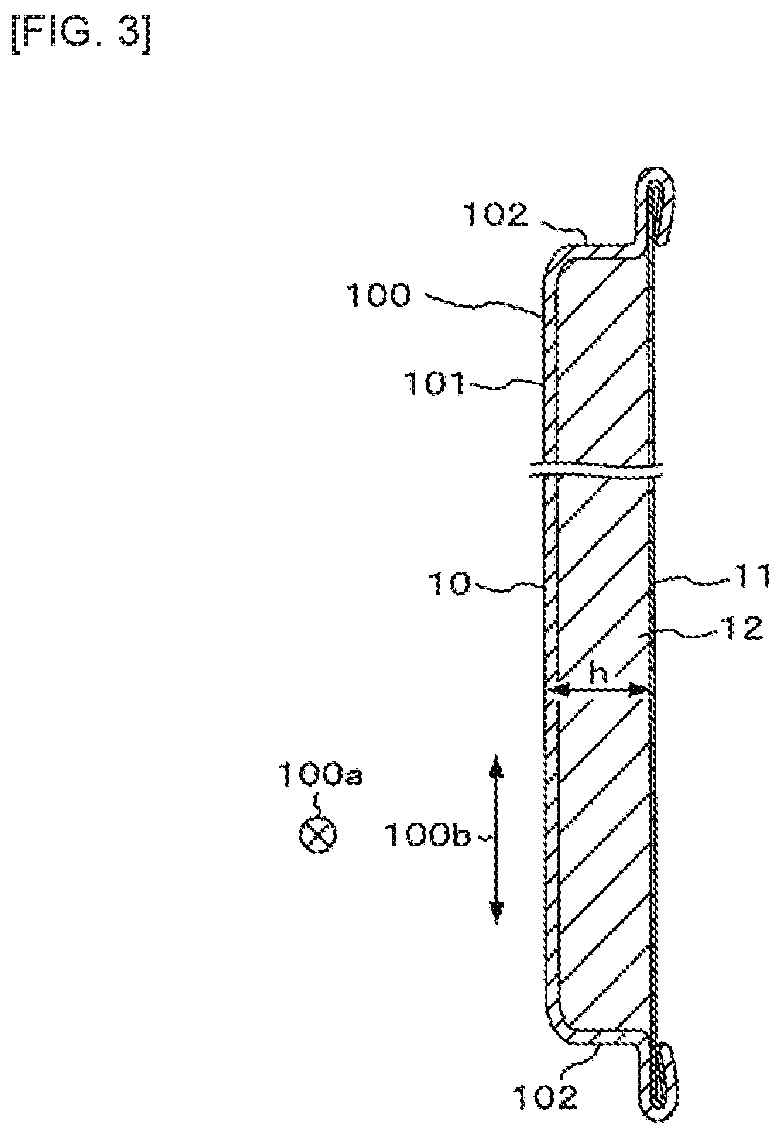
[0025]FIG. 1 is a front view showing a metal roofing material subjected to a method for testing strength of a metal roofing material according to Embodiment 1 of the present invention, FIG. 2 is a back view showing the metal roofing material 1 in FIG. 1, FIG. 3 is a cross-sectional view of the metal roofing material 1 taken along the line III-III in FIG. 1, and FIG. 4 is an explanatory view showing a roofing structure using metal roofing materials 1.

[0026]The metal roofing material 1 shown in FIGS. 1 to 3 is arranged together with other metal roofing materials on a roof base in a roof of a building such as a house, as shown in FIG. 4. As can be particularly seen from FIG. 3, the metal roofing material 1 includes a front substrate 10, a back substrate 11 and a core material 12.

[0027]The front substrate 10 is a metal member that is made of a metal sheet and that appears on the outer surface of the roof as the metal roofing material 1 is placed on the roof base. A steel sheet, an Al sh...

embodiment 2

[0052]FIG. 10 is an explanatory view showing a computer for performing a virtual strength test of the metal roofing material according to Embodiment 2 of the present invention. In the embodiment 1, the test for measuring the load 52L and the uplift amount 1R when the load 52L is actually applied to the metal roofing material 1 has been described, but this test may be virtually performed by a computer 6.

[0053]The computer 6 shown in FIG. 10 includes a storage means and an arithmetic means, and operates in accordance with a virtual strength test program for the metal roofing material stored in the storage means or a readable medium, thereby realize a model creating function 60, a tightening function 61, a load applying function 62, a calculating function 63, and a determining function 64.

[0054]The model creating function 60 is a function of receives an input of property information indicating mechanical properties and material physical properties of the front substrate 10, the back su...


PUM

PropertyMeasurementUnit
depthaaaaaaaaaa
widthaaaaaaaaaa
widthaaaaaaaaaa

Abstract

The present invention provides a method for testing strength of a metal roofing material, the metal roofing material comprising: a front substrate made of a metal sheet; a back substrate arranged on the back side of the front substrate; and a core material filled between the front substrate and the back substrate, the method comprising the steps of: tightening the metal roofing material 1 to a base 50; and applying a load 52L for uplifting an end portion 1E of the metal roofing material 1 tightened to the base 50 to the end portion 1E and measuring an uplift amount of the end portion 1E corresponding to the load 52L.

Description

[0001]The present application is a U.S. National Stage of PCT International Patent Application No. PCT / JP2017 / 008785, filed Mar. 6, 2017, which claims priority to JP Application No. 2016-050805, filed Mar. 15, 2016, both of which are hereby incorporated herein by referenceTECHNICAL FIELD[0002]The present invention relates to a strength test method for a metal roofing material, strength test equipment and a virtual strength test program, for testing the metal roofing material.BACKGROUND ART[0003]For example, a roofing material for forming roofs of buildings such as houses can include a ceramic roofing material as disclosed in Patent Document 1 and the like described below. Strength of such a ceramic roofing material is tested by a method defined in the Japanese Industrial Standard A 1408. That is, the strength test of the ceramic roofing material is carried out by cutting out a test piece having predetermined dimensions from the ceramic roofing material, and then placing the test pie...

Claims


Application Information

Patent Timeline
Patent Type & Authority Patents(United States)
IPC IPC(8): G01N3/20G01N3/08E04D1/18E04D1/28G06F30/17G06F30/20
CPCG01N3/20E04D1/18E04D1/28G01N3/08G06F30/17G06F30/20G01N2203/0017G01N2203/0091G01N3/14G01N2203/0033
Inventor NORITA, KATSUNARINOGUCHI, KEITAMIURA
Owner NISSHIN STEEL CO LTD
Learn More