Illumination apparatus for a vehicle with light sources, guide elements and optical separation function

a technology of illumination apparatus and vehicle, applied in the field of lighting devices, can solve the problems of large installation space for known lighting devices, and achieve the effect of reducing the installation space of known lighting devices

Active Publication Date: 2022-01-25
HELLA KG HUECK & CO
View PDF17 Cites 0 Cited by
  • Summary
  • Abstract
  • Description
  • Claims
  • Application Information

AI Technical Summary

Benefits of technology

[0005]It is therefore an object of the present invention to provide a lighting device for vehicles such that, in a space-saving manner, a plurality of luminous graphics different with respect to brightness and / or color can be generated with a clear channel separation to avoid scattered light or stray light.
[0007]The lighting device can have a plurality of micro light guide elements, each of which is assigned a single light source. The relatively small-dimensioned micro light guide element / light source pairs enable a light distribution or luminous graphic of high resolution. By appropriately controlling the light sources, the luminous graphic can have predetermined areas of high and low brightness or of a first and second color. In this way, luminous graphics of a specific pattern can advantageously be generated in terms of area and / or time. The integration of optical separations between adjacent micro light guide elements ensures that no scattered light portion of a light from a first light source assigned to a first micro light guide element is emitted via an adjacent micro light guide element. A luminous graphic can thus advantageously be provided, for example, with a color pattern of high resolution and little blurring. The optical separations lead to a channeling of the light, wherein the micro light guide elements exclusively transform or emit the light from the light sources assigned to them. An undesired crossing or shining over of light from neighboring “light channels” can thus be safely avoided. The lighting device according to the invention thus enables true-to-color and sharp luminous graphics.
[0012]The optical separations can each be designed as separating webs that rise from a base surface of a separating web unit and in the assembly position each engage in recesses of a microlens unit which receives the microlenses. The base surface of the separating web unit lies flat against a base surface of the microlens unit. This advantageously ensures simple assembly, wherein a defined relative position between the lenses and light sources arranged in pairs can be achieved. The separating web unit or the separating webs are guided in the direction of the light source area of extent up to the level of the light emitting surface of the light source and, ideally, are guided to the plane of the printed circuit board.
[0014]The separating web carrier and the microlens unit can be produced by two-component injection molding from an opaque and a translucent component. In this way, a microlens arrangement provided with separating webs can advantageously be produced in a simple and rapid manner.
[0015]The separating web unit can be formed by a separate metal part that is produced, for example, by die casting. In this way, relatively small wall thicknesses of the optical separations can advantageously be achieved. On the front side, the separating web unit can be overmolded with a transparent plastic material to form the microlens elements, wherein the optical separating webs are overmolded tightly.

Problems solved by technology

For generating such “intelligent” luminous graphics, the known lighting device has the disadvantage of requiring a relatively large installation space.

Method used


Image

  • Illumination apparatus for a vehicle with light sources, guide elements and optical separation function
  • Illumination apparatus for a vehicle with light sources, guide elements and optical separation function
  • Illumination apparatus for a vehicle with light sources, guide elements and optical separation function

Examples


Embodiment Construction

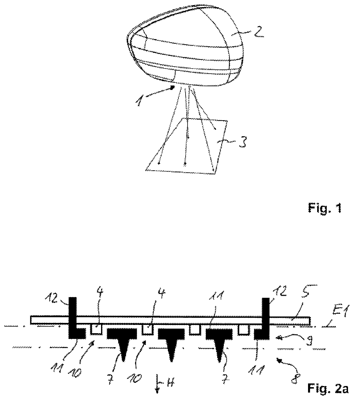
[0035]A lighting device according to the invention is preferably designed as an entrance light 1 which is integrated in an outside mirror 2 of a vehicle. The entrance light 1 is used to generate a luminous graphic 3, by means of which an area in front of a driver's door of the vehicle is illuminated. The entrance light 1 has a control which can be activated by the driver, for example, by means of a central remote control of the vehicle key.

[0036]Alternatively, the lighting device according to the invention can also be arranged in a trim strip along the doors of the vehicle or in lateral vehicle sills below the doors or in the area of a front and / or rear wheelhouse of the vehicle. Alternatively, the lighting device can be arranged in the interior of the vehicle to illuminate an illumination range in the interior, for example, to illuminate fixed, predetermined illumination ranges of the dashboard or the center console.

[0037]As a light source unit, the entrance light 1 comprises a plu...


PUM


Abstract

A lighting device for vehicles with a plurality of light sources and with a plurality of light guide elements each assigned to each of the light sources, which are arranged in front of the light sources in the main emission direction, wherein the light guide elements are designed as micro light guide elements and that an optical separation is provided between neighboring micro light guide elements and / or in the main radiation direction behind the micro light guide elements so that a scattered light portion emitted by a first light source cannot be irradiated or emitted by a light guide element assigned to a second light source.

Description

[0001]This nonprovisional application is a continuation of International Application No. PCT / EP2019 / 053544, which was filed on Feb. 13, 2019, and which claims priority to German Patent Application No. 10 2018 106 035.1, which was filed in Germany on Mar. 15, 2018, and which are both herein incorporated by reference.BACKGROUND OF THE INVENTIONField of the Invention[0002]The present invention relates to a lighting device for vehicles with a plurality of light sources and with a plurality of light guide elements each assigned to the light sources, which are arranged in the main emission direction in front of the light sources.Description of the Background Art[0003]A lighting device for vehicles is known from DE 10 2009 023 916 B4, which has a plurality of light sources and a plurality of light guide elements designed as lenses for generating a predetermined light distribution. A lens element is assigned to each of the light sources so that, for example, an elongated surface of an addit...

Claims


Application Information

Patent Timeline
Patent Type & Authority Patents(United States)
IPC IPC(8): F21S43/50F21S43/14F21S43/15F21S43/20F21Y113/10F21Y115/10F21W103/60F21W103/15
CPCF21S43/50F21S43/14F21S43/15F21S43/26F21W2103/15F21W2103/60F21Y2113/10F21Y2115/10B60Q1/2665B60Q1/323B60Q3/745B60Q2400/50
Inventor MUEGGE, MARTIN
Owner HELLA KG HUECK & CO
Why Eureka
Try Eureka