Multipolar connector

a multi-polar connector and connector technology, applied in the field of signal connection, can solve the problems of affecting shielding and isolation, difficult to accurately locate the shielding component, etc., and achieve the effect of improving the shielding effect and difficult to be accurately located

Active Publication Date: 2021-12-28
AAC TECH PTE LTD
View PDF28 Cites 0 Cited by
  • Summary
  • Abstract
  • Description
  • Claims
  • Application Information

AI Technical Summary

Benefits of technology

[0013]Compared with the related arts, the multipolar connector of the present disclosure integrates the shielding component and the outer terminal as one piece to avoid the issue that the shielding component is difficult to be accurately located when the shielding component is separately inserted into the insulating component (inaccurate location of the shielding component when the shielding component is separately inserted into the insulating component will weaken the shielding and isolation effect of shielding component), so as to improve the shielding effect.

Problems solved by technology

There is no shielding component inside of the connector, which leads to signal interference between the inner terminals; or, a shielding component is independently embedded in the insulating component and separated from the outer terminal, thereby affecting shielding and isolation effect to a certain extent.
In addition, it is difficult to accurately locate the shielding component during separately inserting the shielding component into the insulating component.

Method used


Image

  • Multipolar connector
  • Multipolar connector
  • Multipolar connector

Examples


embodiment i

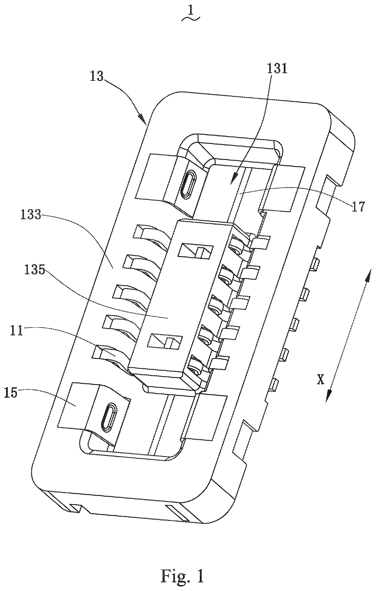
[0032]A multipolar connector as shown in FIG. 7 is formed by mutual engagement as shown in FIG. 6 of a first connector 1 as shown in FIG. 1 and a second connector 3 as shown in FIG. 4. The first connector 1 and the second connector 3 are connected to different circuit substrates (not shown), respectively. These circuit substrates are electrically connected by the multipolar connector which is formed by mutual engagement of the first connector 1 and the second connector 3.

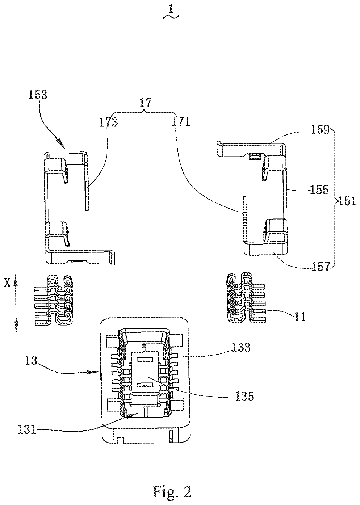
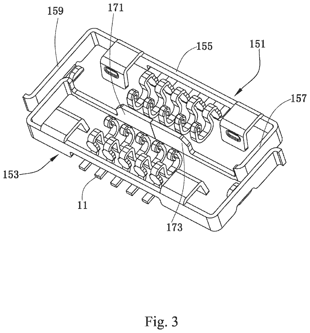
[0033]As shown in FIG. 1, FIG. 2 and FIG. 3, the first connector 1 includes a plurality of inner terminals 11, an insulating component 13, outer terminals 15 and a shielding component 17.

[0034]The plurality of inner terminals 11 are arranged in a plurality of columns, and each column has several inner terminals 11. In an exemplary embodiment as shown in FIG. 1 and FIG. 2, the plurality of inner terminals 11 are arranged in two columns, and each column is arranged with five inner terminals 11. An orientation of one c...

embodiment ii

[0053]As shown in FIG. 9 which only shows the shielding component and the outer terminal, the difference between the second embodiment and the first embodiment is as following: the shielding component 17 of the second embodiment has an integral structure, and both ends of the shielding component 17 are integrated to the first transverse side 157 of the first outer terminal 151 and the first transverse side 157 of the second outer terminal 153, respectively. In other words, the first outer terminal 151, the second outer terminal 153, and the shielding component 17 are integrally formed as one piece.

embodiment iii

[0054]As shown in FIG. 10 which only shows the shielding component and the outer terminal, the difference between the third embodiment and the second embodiment is as following: the shielding component 17 extends from the first transverse side 157 of the first outer terminal 151 to the first transverse side 157 of the second outer terminal 153 along the X direction. An end of the shielding component 17 away from the first transverse side 157 of the first outer terminal 151 can be separated from the first transverse side 157 of the second outer terminal 153, or can be in contact with the first transverse side 157 of the second outer terminal 153. In other words, the first outer terminal 151 and the shielding component 17 are integrally formed as one piece.


PUM


Abstract

A multipolar connector includes a first connector and a second connector. The first connector includes inner terminals arranged in columns and an insulating component holding the inner terminals. The second connector includes inner terminals arranged in columns and an insulating component holding the inner terminals. One of the first connector and second connector further includes an outer terminal connected to the ground potential and held by the insulating component. A shielding component extends from the outer terminal along a direction in which the columns of inner terminals extend and is held by the insulating component, and the shielding component is located between adjacent columns of inner terminals when the inner terminals of the first connector and second connector are in contact and engaged with each other. Compared with the related art, the multipolar connector of the present disclosure does not need to form the shielding component by separately insert-molding.

Description

FIELD OF THE INVENTION[0001]The present disclosure relates to the technical field of signal connection, and in particular to a multipolar connector formed by engagement of multi connectors.BACKGROUND OF THE INVENTION[0002]Nowadays, rapid development of electronic technology makes the electronic devices be widely used. A variety of circuit substrates with different functions are arranged in the electronic devices to meet user's various functional requirements for the electronic devices. Currently, a multipolar connector is generally used to electrically connect two circuit substrates.[0003]A single connector of a conventional multipolar connector is consisted of inner terminals, an insulating component, and an outer terminal (metal housing). There is no shielding component inside of the connector, which leads to signal interference between the inner terminals; or, a shielding component is independently embedded in the insulating component and separated from the outer terminal, thereb...

Claims


Application Information

Patent Timeline
Patent Type & Authority Patents(United States)
IPC IPC(8): H01R12/71H01R12/55H01R13/11H01R13/502H01R13/6585
CPCH01R12/716H01R12/55H01R13/113H01R13/502H01R13/6585H01R13/6581H01R13/516H01R13/6597
Inventor CHEN, YONGLIWANG, YAZHANG, HUA
Owner AAC TECH PTE LTD
Why Eureka
Try Eureka