
Diagnostic system for a lubrication circuit

a lubricating circuit and diagnostic system technology, applied in the direction of instruments, mechanical equipment, material analysis, etc., can solve the problems of not providing a reliable measure, not allowing a correct evaluation of the capacity of the same to adequately fulfill the functions, and not allowing an accurate assessment of the state of the lubricating liquid

Active Publication Date: 2021-12-28
VHIT SPA
View PDF14 Cites 0 Cited by
  • Summary
  • Abstract
  • Description
  • Claims
  • Application Information

AI Technical Summary

Benefits of technology

The present invention is a diagnostic system for monitoring the condition of a lubrication circuit in an internal combustion engine of a vehicle. The system includes a viscometer and temperature sensor to detect the viscosity and temperature of the lubricating liquid. The system also includes a database to store reference values for the viscosity of the lubricating liquid based on the condition of use of the engine, such as the speed of the engine or the distance traveled by the vehicle. The system can evaluate the condition of the lubricating liquid by comparing the detected viscosity with the reference values. The control unit can activate signals indicating the need for replacement of the lubricating liquid or the need for regeneration of the filter based on the detected viscosity. The control unit can also activate signals indicating the need for reduction of the vehicle speed or the need for a recovery mode of the engine. The control unit can vary the flow rate of the lubricating liquid based on the detected viscosity and can activate the addition of additives to the lubricating liquid based on the detected viscosity.

Problems solved by technology

However, the kilometers traveled by the vehicle do not provide a reliable measure of the actual state of the lubricating liquid, and therefore do not allow a correct evaluation of the capacity of the same to adequately fulfill its functions.
The conventional device, however, basing the evaluation of the lubricating liquid on the viscosity and temperature thereof, does not allow an accurate assessment of the state of the lubricating liquid.

Method used


Image

  • Diagnostic system for a lubrication circuit

Examples


Embodiment Construction

[0021]These and other features and advantages of the present invention will become more apparent from the following description of preferred embodiments of the present invention, given by way of non-limiting example with reference to the figures, in which elements indicated by the same or similar reference numeral indicate elements having the same of similar functionality and structure.

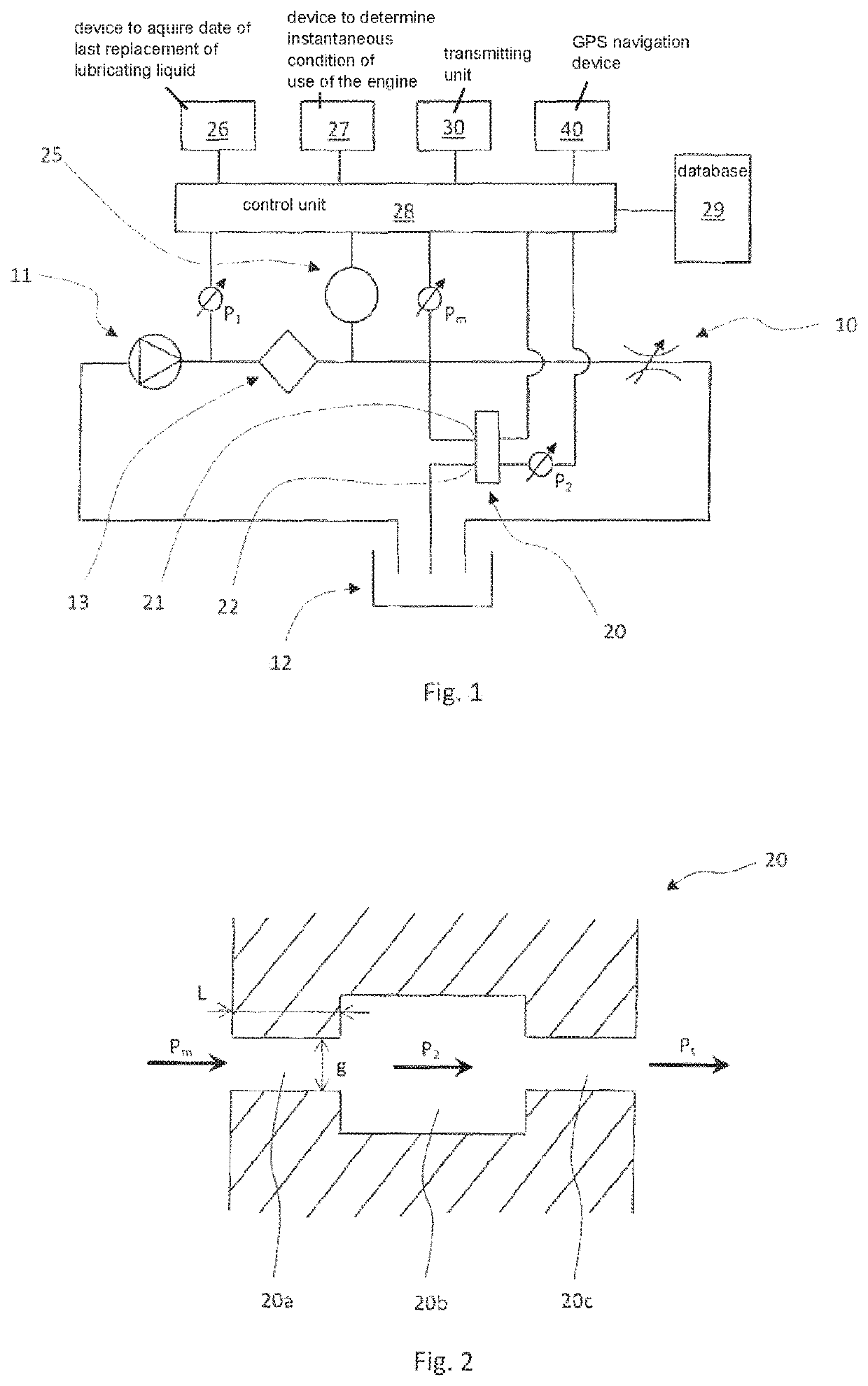
[0022]FIG. 1 is a schematic view showing an example diagnostic system of a lubrication circuit according to the present invention.

[0023]FIG. 2 is a schematic view of a viscometer used in a diagnostic system according to the present invention.

DESCRIPTION OF SOME PREFERRED EMBODIMENTS OF THE INVENTION

[0024]Referring to FIG. 1, a diagnostic system is applied to a lubrication circuit of a combustion engine (engine) 10 of a vehicle.

[0025]The lubrication circuit includes, in addition to the engine 10, a lubricating liquid pump (pump) 11 adapted to draw lubricating liquid from a lubricating liquid tank 12 an...


PUM

PropertyMeasurementUnit
temperaturesaaaaaaaaaa
viscosityaaaaaaaaaa
temperatureaaaaaaaaaa

Abstract

A diagnostic system for a lubrication circuit of an internal combustion engine of a vehicle. The system includes a viscometer for detecting the viscosity of a lubricating liquid of the lubrication circuit, a temperature sensor for detecting the temperature of the lubricating liquid, and a control unit to acquire the state of the lubricating liquid, given by the viscosity detected for a given lubricating liquid condition, which includes the lubricating liquid temperature and the date of last replacement of the lubricating liquid, and for a given condition of use of the engine, and to assess the state of the lubricating liquid by comparing the detected viscosity of the lubricating liquid with the viscosity reference values stored in the database in the same or similar condition of lubricating liquid temperature, date of last replacement of the lubricating liquid and use of the engine.

Description

FIELD[0001]The present invention generally relates to a diagnostic system for a lubrication circuit of internal combustion engines. More particularly, the diagnostic system is based on the detection of the viscosity of lubricating liquid of the lubrication circuit. The diagnostic system finds application especially in the automotive field.BACKGROUND INFORMATION[0002]In the automotive field, a lubricating liquid is conventionally used for lubricating internal combustion engines by means of suitable lubrication circuits. In addition to lubricating the moving parts of an engine, the lubricating liquid also performs the function of keeping the engine clean, protecting it from corrosion, improving sealing thereof and cooling it by discharging the heat from the moving parts.[0003]The lubricating liquid undergoes a deterioration process during its use and therefore it must be replaced periodically. The most common current systems provide for the replacement of the lubricating liquid on the...

Claims


Application Information

Patent Timeline
Patent Type & Authority Patents(United States)
IPC IPC(8): G01N33/28F01M1/18F01M11/10F16N29/04
CPCF01M11/10G01N33/2888F01M1/18F01M2011/148F16N29/04F16N2250/08F16N2250/36F16N2200/12F16N2270/52
Inventor FAUDA, ALESSANDROANDREOLLI, GABRIELECADEDDU, LEONARDOMARCHETTI, LUCIANOCROSIO, PIETRO FRANCESCO
Owner VHIT SPA
Learn More