Thermal conductivity measuring device, thermal conductivity measuring method and vacuum evaluation device

a technology of thermal conductivity and measuring device, which is applied in the direction of material thermal conductivity, heat measurement, instruments, etc., can solve the problems of long period of time and difficulty in accurately measuring thermal conductivity in a short period of time, and achieve the effect of accurate thermal conductivity, short period of time and high efficiency

Active Publication Date: 2021-12-07
EKO INSTR
View PDF6 Cites 0 Cited by
  • Summary
  • Abstract
  • Description
  • Claims
  • Application Information

AI Technical Summary

Benefits of technology

[0017](Effect of the Invention) The present invention allows for measuring accurate thermal conductivity in a short period of time. Also, the present invention allows for evaluating the degree of vacuum with high efficiency in a short period of time.
) The present invention allows for measuring accurate thermal conductivity in a short period of time. Also, the present invention allows for evaluating the degree of vacuum with high efficiency in a short period of time.

Problems solved by technology

In the methods described in Patent Documents 1 and 2, however, it is difficult to measure thermal conductivity accurately in a short period of time.
In other words, although it is desirable to use the output of a thermocouple at a time when the temperature change of an object to be measured reaches a certain steady state in order to accurately measure the thermal conductivity, it generally takes time for the temperature rise to reach a steady state, and a long period of time is required particularly for vacuum insulation panels having low thermal conductivity.

Method used


Image

  • Thermal conductivity measuring device, thermal conductivity measuring method and vacuum evaluation device
  • Thermal conductivity measuring device, thermal conductivity measuring method and vacuum evaluation device
  • Thermal conductivity measuring device, thermal conductivity measuring method and vacuum evaluation device

Examples


Embodiment Construction

[0026]Next, the following describes the aspect for implementing the present invention in detail with reference to drawings.

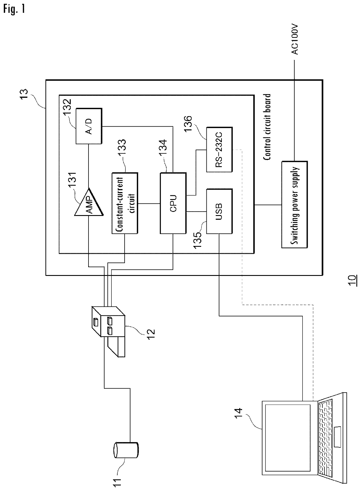
[0027](Aspect of Implementation) FIG. 1 is a view showing the configuration of a thermal conductivity measuring device 10 according to one embodiment of the present invention. As shown in FIG. 1, the thermal conductivity measuring device 10 comprises a measuring section 11, a display device 12, a control device 13, and a computer (a calculating device, a vacuum evaluating section) 14. The measuring section 11, the display device 12, the control device 13, and the computer 14 are connected to each other via telecommunication lines. The thermal conductivity measuring device 10 may comprise a barcode reader, a QR code® reader or the like as needed so that a barcode provided on an object to be measured can be read and the object to be measured can automatically be identified.

[0028]The thermal conductivity measuring device 10 is a device for measuring the thermal con...


PUM

PropertyMeasurementUnit
internal resistanceaaaaaaaaaa
outer diameteraaaaaaaaaa
widthaaaaaaaaaa

Abstract

The object of the invention is to provide a thermal conductivity measuring device that comprises a heat generator arranged in such a way as to come into contact with an object to be measured for thermal conductivity, a heat resistant material arranged in such a way as to come into contact with the heat generator, at least one pair of differential thermocouples for measuring a voltage value caused by the difference in temperature of two points of the heat resistant material, the temperature being generated by allowing heat to flow from the heat generator, and a calculating device for calculating the time rate of change of output voltage of the differential thermocouples and then calculating the thermal conductivity of the object to be measured on the basis of the calculated time rate of change.

Description

FIELD OF THE INVENTION[0001]The present invention relates to a thermal conductivity measuring device, a thermal conductivity measuring method and a vacuum evaluation device.BACKGROUND OF THE INVENTION[0002]A vacuum insulation panel (VIP) has been used more and more not only in refrigerators but housing construction materials as well, because its thermal insulation efficiency is so high that energy saving effects can be achieved. The vacuum insulation panel declines in its performance due to a decrease in the degree of vacuum caused by leakage or the like; since it is difficult to confirm the decline visually, it is essential to measure thermal conductivity. Methods for measuring the thermal conductivity of a specimen include those described in Patent Documents 1 and 2 (U.S. Pat. No. 6,676,287 and Japanese Patent Application Kokai Publication No. 2013-88258).SUMMARY OF THE INVENTION[0003]In the methods described in Patent Documents 1 and 2, however, it is difficult to measure thermal...

Claims


Application Information

Patent Timeline
Patent Type & Authority Patents(United States)
IPC IPC(8): G01N25/18G01K7/02G01K7/00G01K3/04
CPCG01N25/18
Inventor HASEGAWA, TOSHIKAZUGOTO, YUKIHIROCHIBA, ISAMU
Owner EKO INSTR
Why Eureka
Try Eureka