
Regenerative oxidizer arrangement

a regenerative oxidizer and arrangement technology, applied in the direction of catalytic material combustion, combustion types, furnaces, etc., can solve the problems of reducing so as to reduce the number of moving parts, reduce the overall efficiency of the rto, and reduce the effect of pressure fluctuations during us

Active Publication Date: 2021-11-23
DUSTEX LLC
View PDF35 Cites 0 Cited by
  • Summary
  • Abstract
  • Description
  • Claims
  • Application Information

AI Technical Summary

Benefits of technology

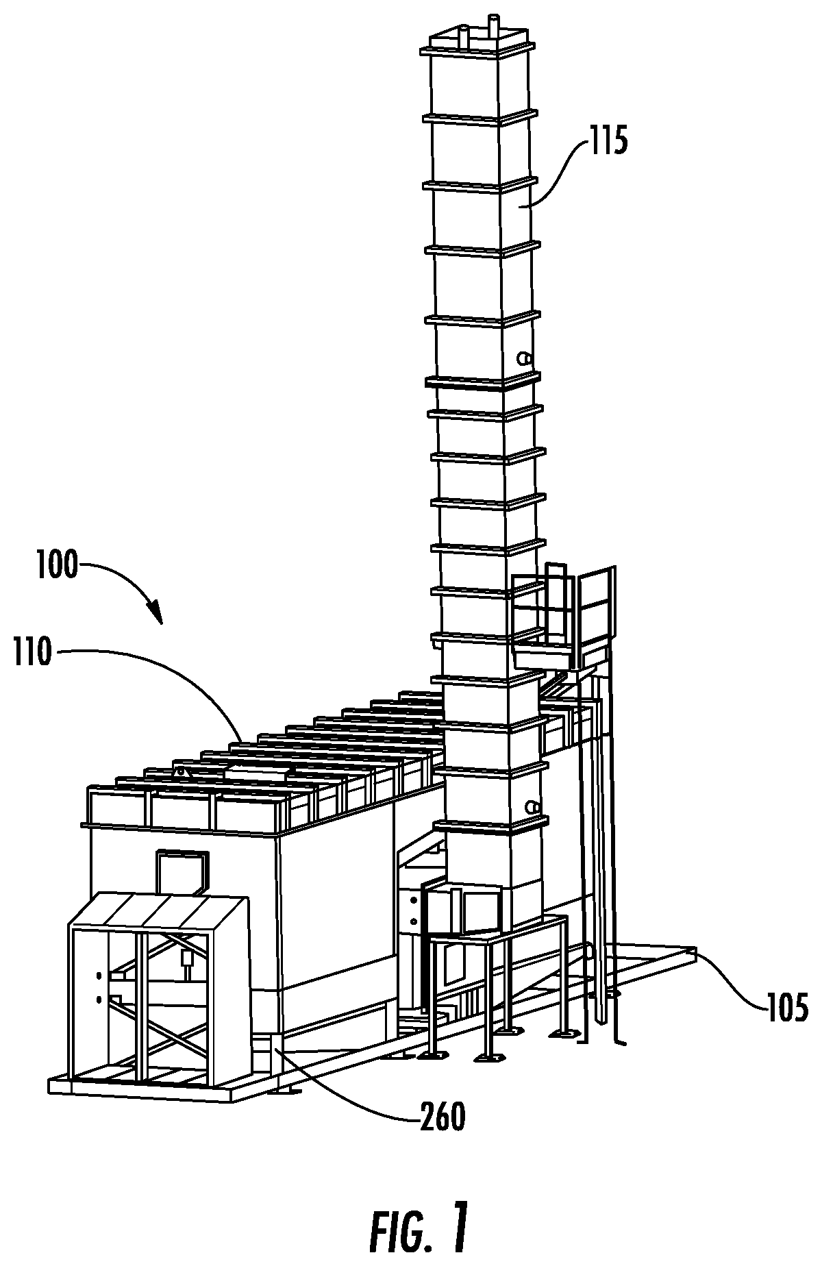
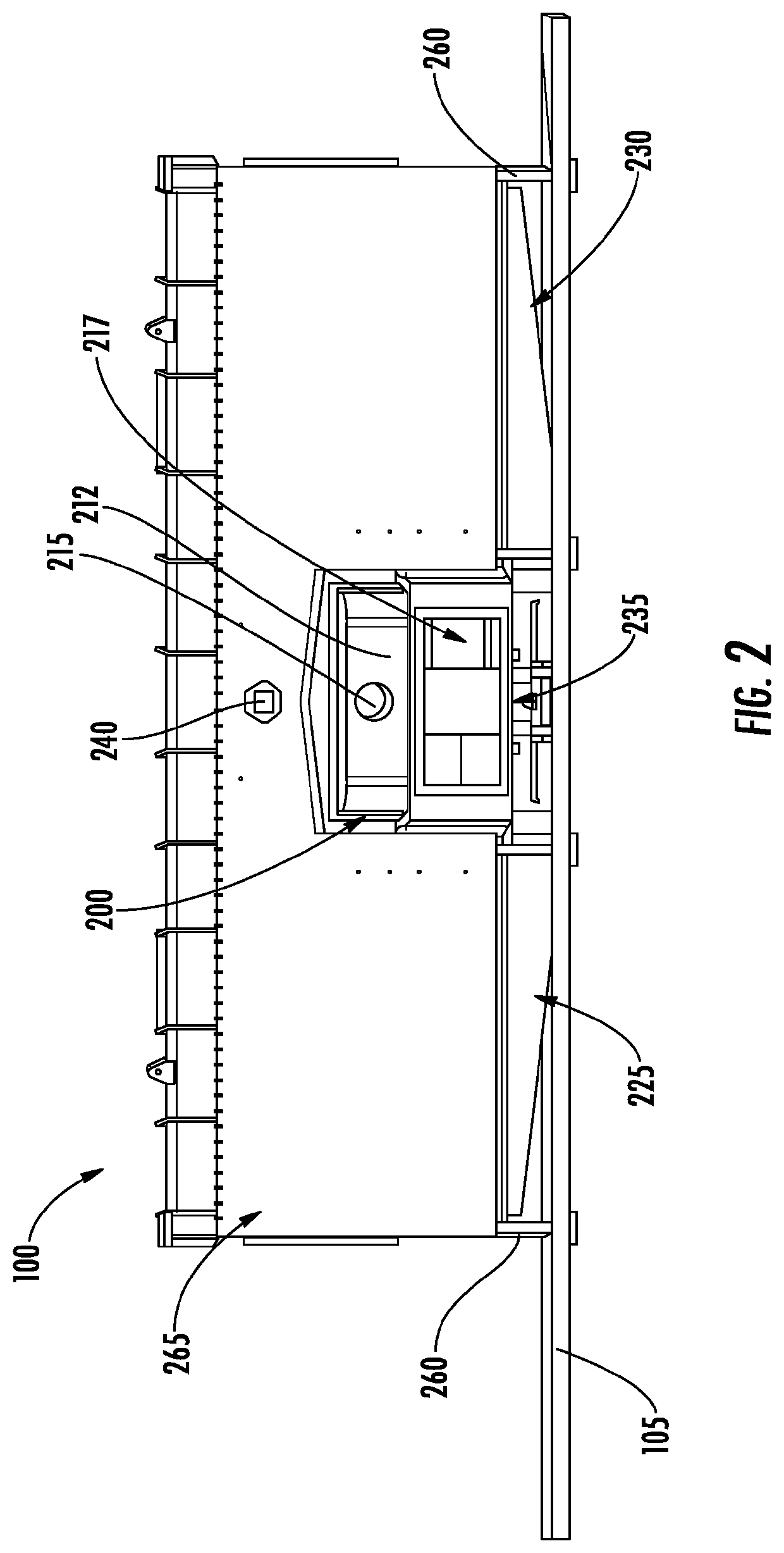
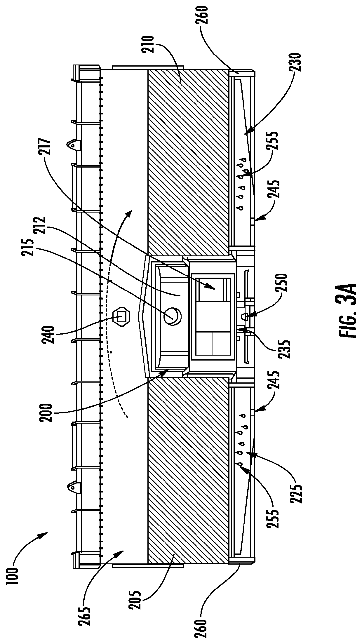
[0003]Traditional RTOs may include various types of diverter valve assemblies including poppet valves, butterfly valves, and rotary valves, each with advantages and disadvantages. Poppet valve RTOs and butterfly valve RTOs require multiple valves to operate as desired. The frequency of valve opening and closing during usage, however, creates a strain on poppet valves, and multiple valves present more potential malfunctions. Rotary valves are used in place of other types of valves to reduce the number of moving parts and lower pressure fluctuations during usage. Conventional rotary valves are positioned below heat exchange media beds resulting in at least two issues. First, during cleaning when water is supplied to the heat exchange media beds to allow for the removal of accumulated inorganic contaminants, dirty water traveling down through the rotary valve may damage the valve seal, resulting in leakage and thereby reducing the overall efficiency of the RTO. Second, conventional rotary valves positioned below the heat exchange media beds do not promote optimal gas flow distribution into the media bed above. Said differently, the gas tends to flow upwardly in a straight line without spreading across the area of the bed. As such, various embodiments described herein relate to methods, apparatuses, and systems that allow for (1) more efficient media bed cleaning, (2) increased manufacturability and improved maintenance due to decreased leg height, (3) a larger combustion chamber for heating passing gases, (4) improved gas distribution within the RTO, (5) gravity assisted valve sealing of the rotary valve, (6) reduced structural steel required in construction, (7) easier access to the heat exchange media beds, and (8) reduced manifold condensation.

Problems solved by technology

The frequency of valve opening and closing during usage, however, creates a strain on poppet valves, and multiple valves present more potential malfunctions.
Conventional rotary valves are positioned below heat exchange media beds resulting in at least two issues.
First, during cleaning when water is supplied to the heat exchange media beds to allow for the removal of accumulated inorganic contaminants, dirty water traveling down through the rotary valve may damage the valve seal, resulting in leakage and thereby reducing the overall efficiency of the RTO.
Second, conventional rotary valves positioned below the heat exchange media beds do not promote optimal gas flow distribution into the media bed above.

Method used


Image

  • Regenerative oxidizer arrangement
  • Regenerative oxidizer arrangement
  • Regenerative oxidizer arrangement

Examples


Embodiment Construction

[0021]Some embodiments of the present disclosure will now be described more fully hereinafter with reference to the accompanying drawings, in which some, but not all embodiments of the disclosure are shown. Indeed, these disclosures may be embodied in many different forms and should not be construed as limited to the embodiments set forth herein; rather, these embodiments are provided so that this disclosure will satisfy applicable legal requirements. Like numbers refer to like elements throughout.

[0022]The components illustrated in the figures represent components that may or may not be present in various embodiments of the invention described herein such that embodiments may include fewer or more components than those shown in the figures while not departing from the scope of the invention. Some components may be omitted from one or more figures or shown in dashed line for visibility of the underlying components.

[0023]The phrases “in an example embodiment,”“some embodiments,”“vari...


PUM


Abstract

Methods and systems for oxidizing gas are provided. An example regenerative oxidizer is provided that includes a combustion chamber to heat gas present in the combustion chamber. The regenerative oxidizer also includes a first heat exchange media bed and a second heat exchange media bed, each in fluid communication with the combustion chamber. The regenerative oxidizer also includes a rotary valve disposed at least partially between the first heat exchange media bed and the second heat exchange media bed. The rotary valve may alternate the flow of gas between a first and a second airflow direction. The first heat exchange media bed, the rotary valve, and the second heat exchange media bed are arranged with respect to each other such that the gas pathway between the first heat exchange media bed and the rotary valve and between the second heat exchange media bed and the rotary valve is non-linear.

Description

FIELD OF THE INVENTION[0001]The present disclosure relates generally to regenerative oxidizers (e.g., regenerative thermal oxidizers (RTOs) and / or regenerative catalytic oxidizers (RCOs)), and, more particularly, to methods, apparatuses, and systems for improving the operability of regenerative thermal oxidizers.BACKGROUND[0002]Regenerative thermal oxidizers (RTOs) are used to reduce the amount of pollutants, such as volatile organic compounds and odors, in gas through thermal oxidation. RTOs may include valve assemblies configured to alternate the flow of gas through the RTO during operation. Through applied effort, ingenuity, and innovation, many identified problems have been solved by developing solutions that are included in embodiments of the present disclosure, many examples of which are described in detail herein.BRIEF SUMMARY[0003]Traditional RTOs may include various types of diverter valve assemblies including poppet valves, butterfly valves, and rotary valves, each with ad...

Claims


Application Information

Patent Timeline
Patent Type & Authority Patents(United States)
IPC IPC(8): F23G7/06F23L15/02F27D17/00F16K11/085F16K31/04
CPCF23G7/068F16K11/085F16K31/041F23L15/02F27D17/008F23C13/06F23G7/07F23J3/02F23N2221/08Y02E20/34
Inventor CASH, JAMES T.
Owner DUSTEX LLC
Learn More