
Key structure

Active Publication Date: 2021-11-16
PRIMAX ELECTRONICS LTD
View PDF2 Cites 4 Cited by
  • Summary
  • Abstract
  • Description
  • Claims
  • Application Information

AI Technical Summary

Benefits of technology

The present invention provides a key structure that reduces noise and improves tactile feel. The elastic buffering element is installed in the locking part, which reduces the rocking condition between the second supporting element and the keycap, resulting in less sound when rotating the second supporting element. Additionally, the elastic buffering element also attenuates high-frequency noise caused by friction between the second supporting element and the bottom surface of the keycap. This improves the stability and feel of the keycap when ascending or descending.

Problems solved by technology

However, while the keycap is moved upwardly or downwardly, the supporting element or the stabilizer bar may readily rub against or collide with the keycap.
Consequently, an unpleasant noise is generated.
As mentioned above, the noise is generated when the supporting element or the stabilizer bar rubs against or collides with the keycap.
However, although the lubricating oil is applied to the region between components, the supporting element or the stabilizer bar may rub against the keycap during rotation.
Under this circumstance, high-frequency noise is generated.
On the other hand, the interference structure for noise reduction may impair the tactile feel of pressing down the key structure.

Method used


Image

  • Key structure
  • Key structure
  • Key structure

Examples


Embodiment Construction

[0031]The present invention will now be described more specifically with reference to the following embodiments. It is to be noted that the following descriptions of preferred embodiments of this invention are presented herein for purpose of illustration and description only. It is not intended to be exhaustive or to be limited to the precise form disclosed.

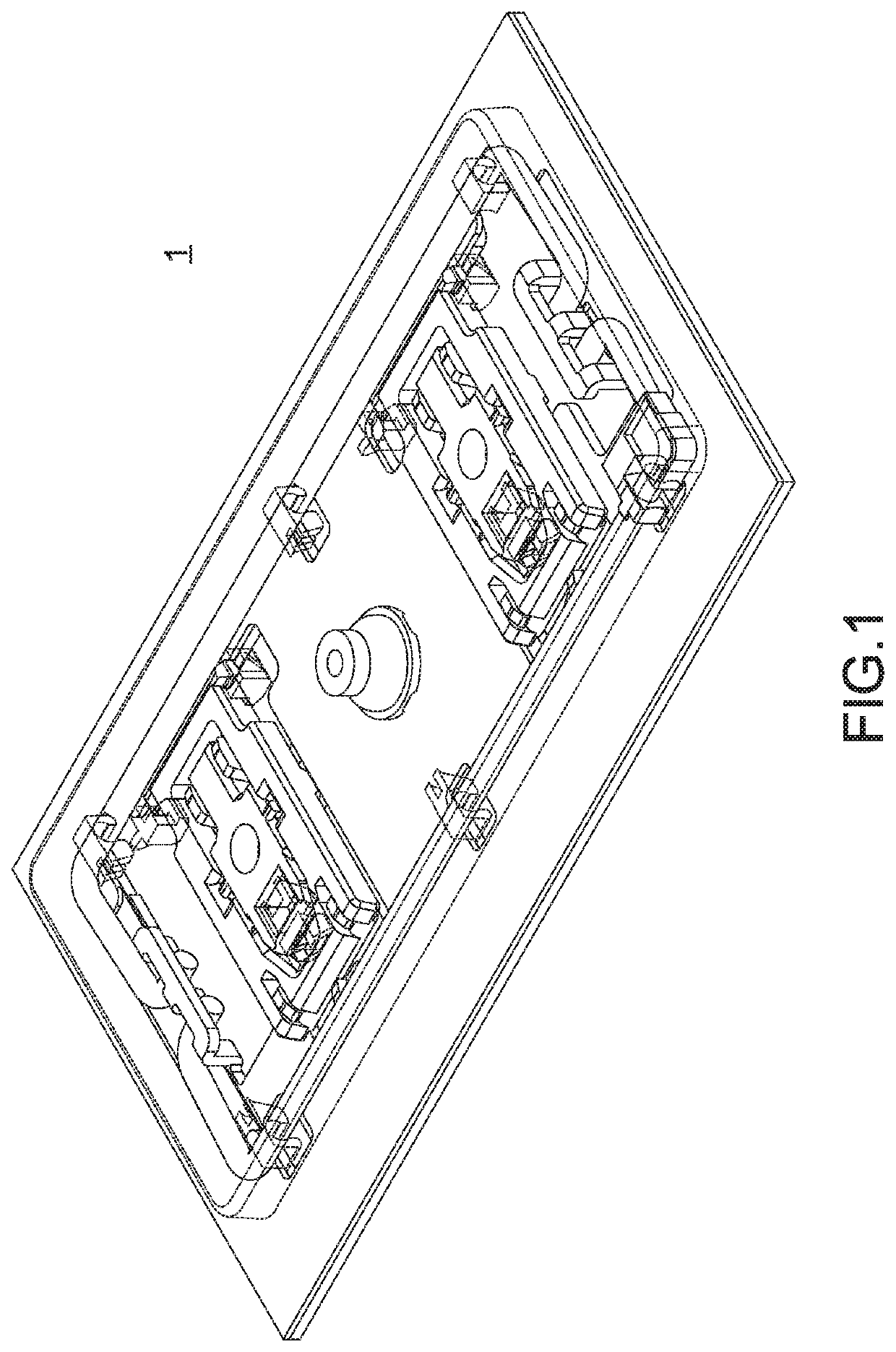
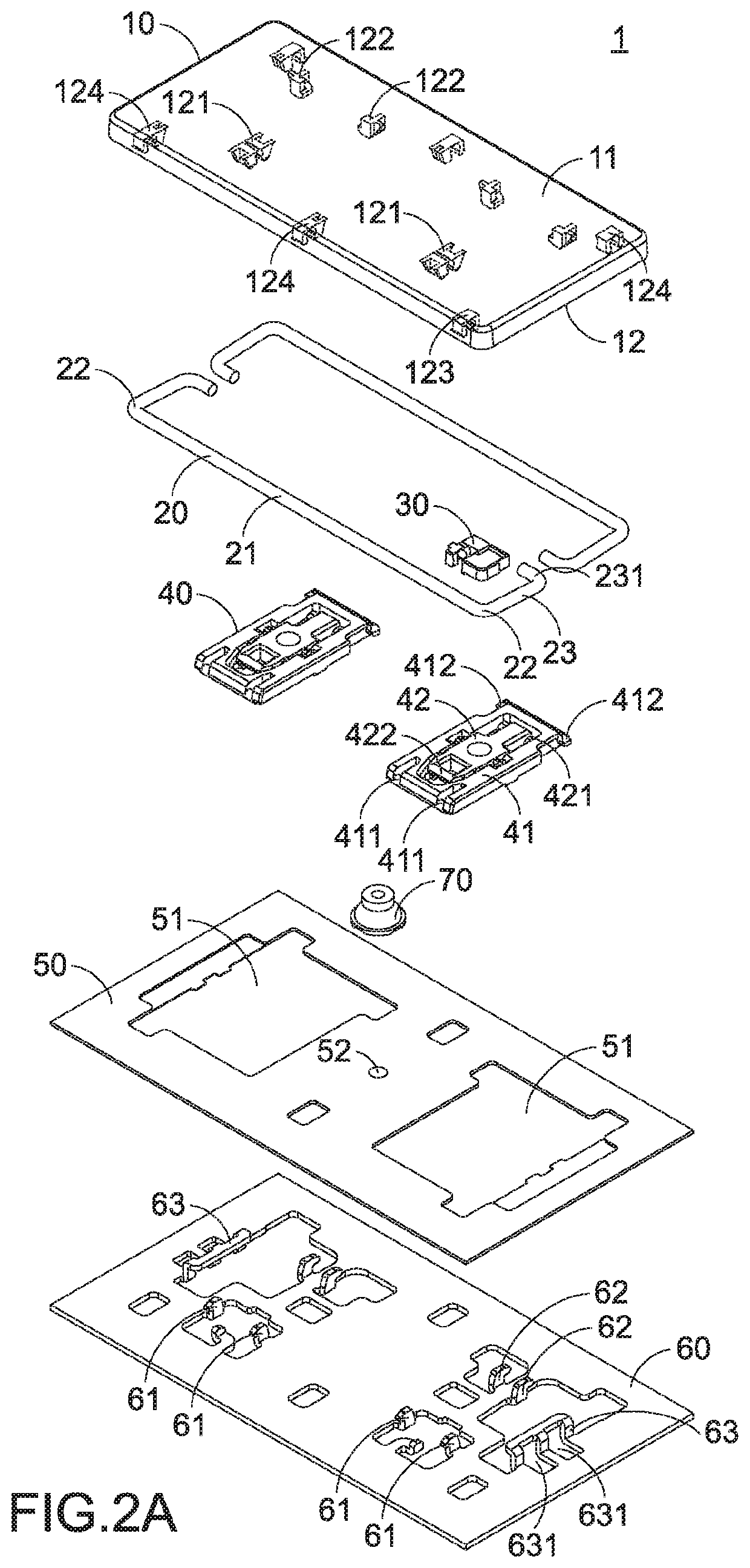
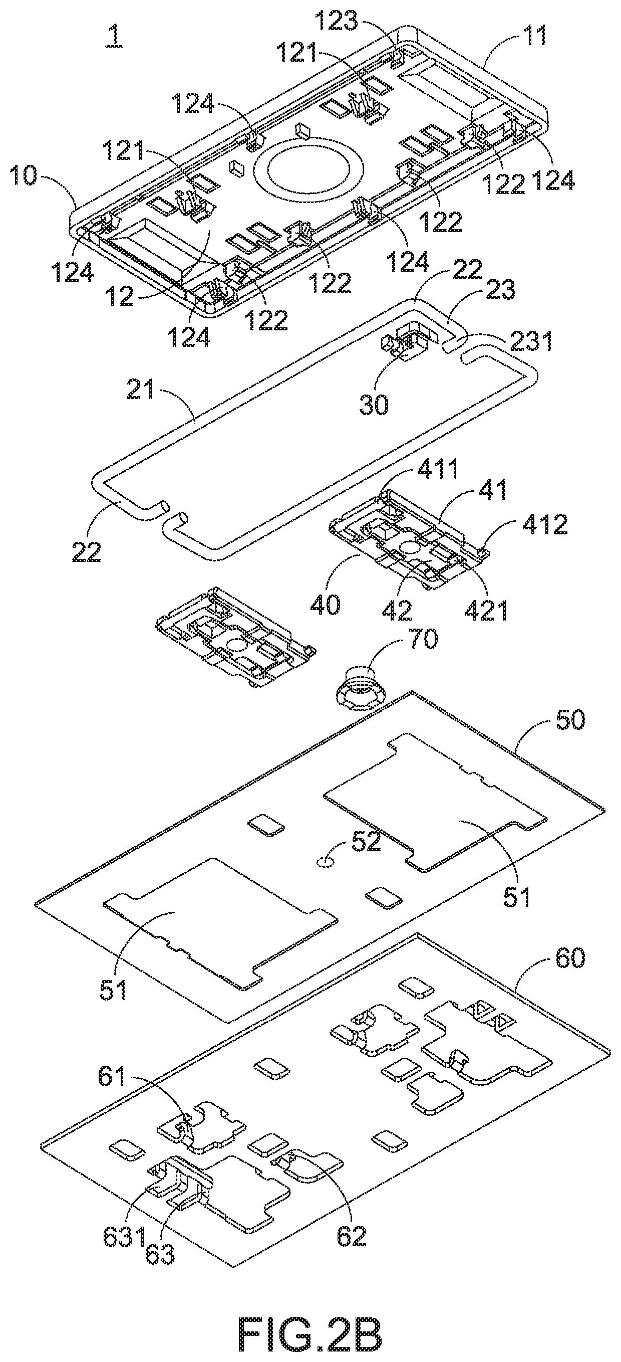
[0032]Please refer to FIGS. 1, 2A and 2B. FIG. 1 is a schematic perspective view illustrating a key structure according to an embodiment of the present invention. FIG. 2A is an exploded perspective view illustrating the key structure according to the embodiment of the present invention and taken along a viewpoint. FIG. 2B is an exploded perspective view illustrating the key structure according to the embodiment of the present invention and taken along another viewpoint. The key structure 1 comprises a keycap 10, at least one second supporting element 20, an elastic buffering element 30, at least one first supporting element 40, a...


PUM


Abstract

A key structure includes a keycap, an elastic buffering element, a base plate, a first supporting element, a second supporting element and an elastomer. The elastic buffering element is installed in a locking part of the keycap. The first supporting element is connected with the keycap and the base plate. The keycap is movable upwardly or downwardly relative to the base plate through the first supporting element. A first end of the second supporting element is pivotally coupled to the base plate. A second end of the second supporting element is penetrated through a pivotal hole of the elastic buffering element and a clamping recess of the locking part. The elastomer is arranged between the keycap and the base plate. An inner diameter of the at least one pivotal hole is slightly smaller than an inner diameter of the clamping recess.

Description

FIELD OF THE INVENTION[0001]The present invention relates to the field of an input device, and more particularly to a key structure.BACKGROUND OF THE INVENTION[0002]In modern societies, electronic products become indispensable parts in human lives. The electronic products are applied in many sectors, including food, clothing, housing, transportation, education and entertainment. Generally, the electronic product comprises a keyboard. For allowing the user to operate the keyboard flexibly, the key structure of the keyboard is usually equipped with a supporting element or a stabilizer bar to increase the overall structural strength of the key structure. The keycap of the key structure is movable upwardly or downwardly relative to a base plate. However, while the keycap is moved upwardly or downwardly, the supporting element or the stabilizer bar may readily rub against or collide with the keycap. Consequently, an unpleasant noise is generated.[0003]As mentioned above, the noise is gen...

Claims


Application Information

Patent Timeline
IPC IPC(8): H01H3/12H01H13/702
CPCH01H3/125H01H13/702H01H2221/052H01H2221/062H01H2233/074
Inventor LIU, CHIEN-HUNG
Owner PRIMAX ELECTRONICS LTD
Learn More