
Power supply apparatus

a power supply and power supply technology, applied in the direction of electrical equipment, emergency protection arrangement details, instruments, etc., can solve the problem of shortening the service life of the power supply apparatus, and achieve the effect of reducing the inrush current of the inpu

Active Publication Date: 2021-11-02
ACER INC
View PDF24 Cites 0 Cited by
  • Summary
  • Abstract
  • Description
  • Claims
  • Application Information

AI Technical Summary

Benefits of technology

The present invention provides a power supply apparatus that can reduce the input inrush current at the moment of activation. This is achieved by connecting an auxiliary capacitor in series with a load capacitor, which leads to a decrease in the capacitance value and a reduction in the input inrush current. This helps to protect the power supply apparatus from damage due to an excessive input inrush current.

Problems solved by technology

An excessive inrush current easily damages parts in the power supply apparatus, which shortens the service life of the power supply apparatus.

Method used


Image

  • Power supply apparatus
  • Power supply apparatus
  • Power supply apparatus

Examples


Embodiment Construction

[0018]In order to make the content of the present invention more comprehensible, embodiments are described below as examples of implementation of the present invention. Wherever possible, the same reference numbers are used in the drawings and the description to refer to the same or like parts, components or steps.

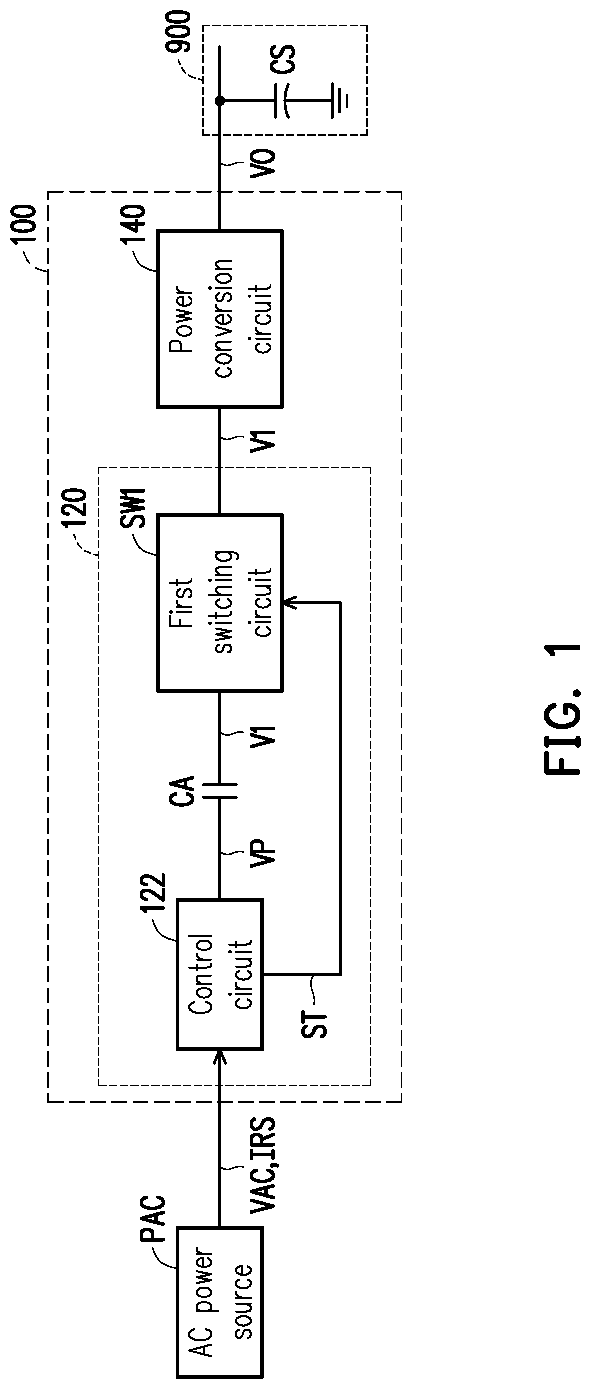
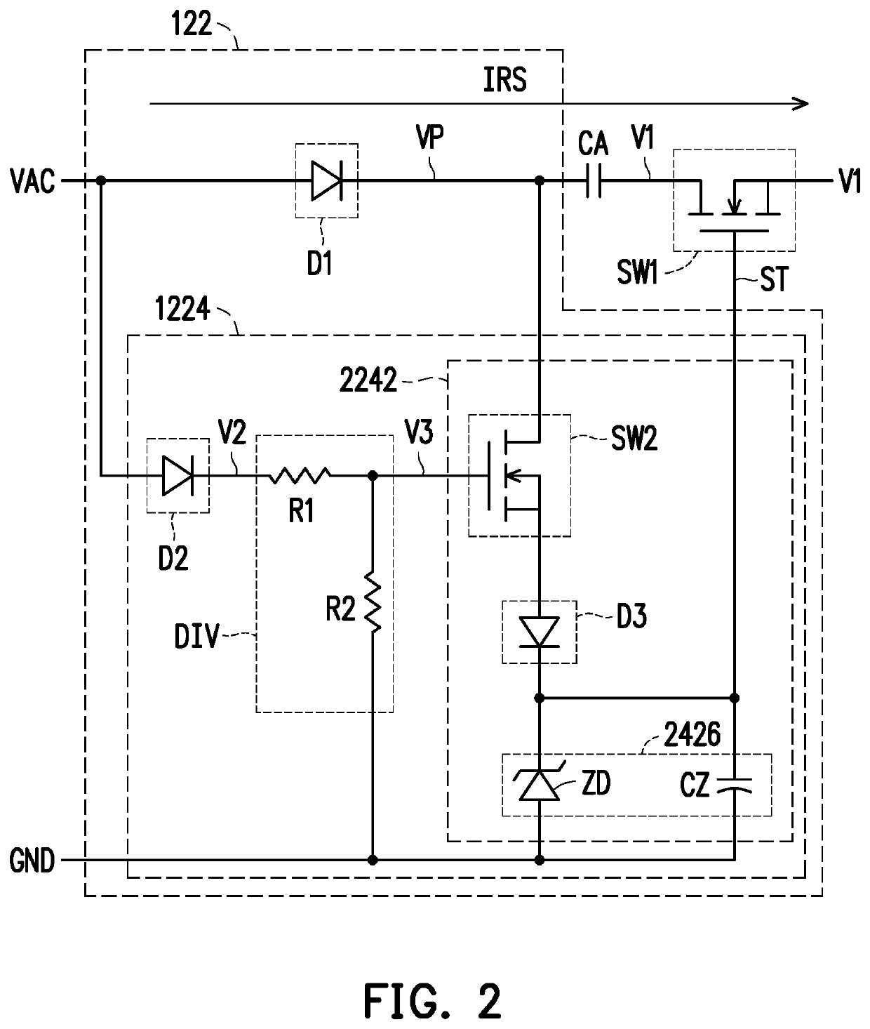
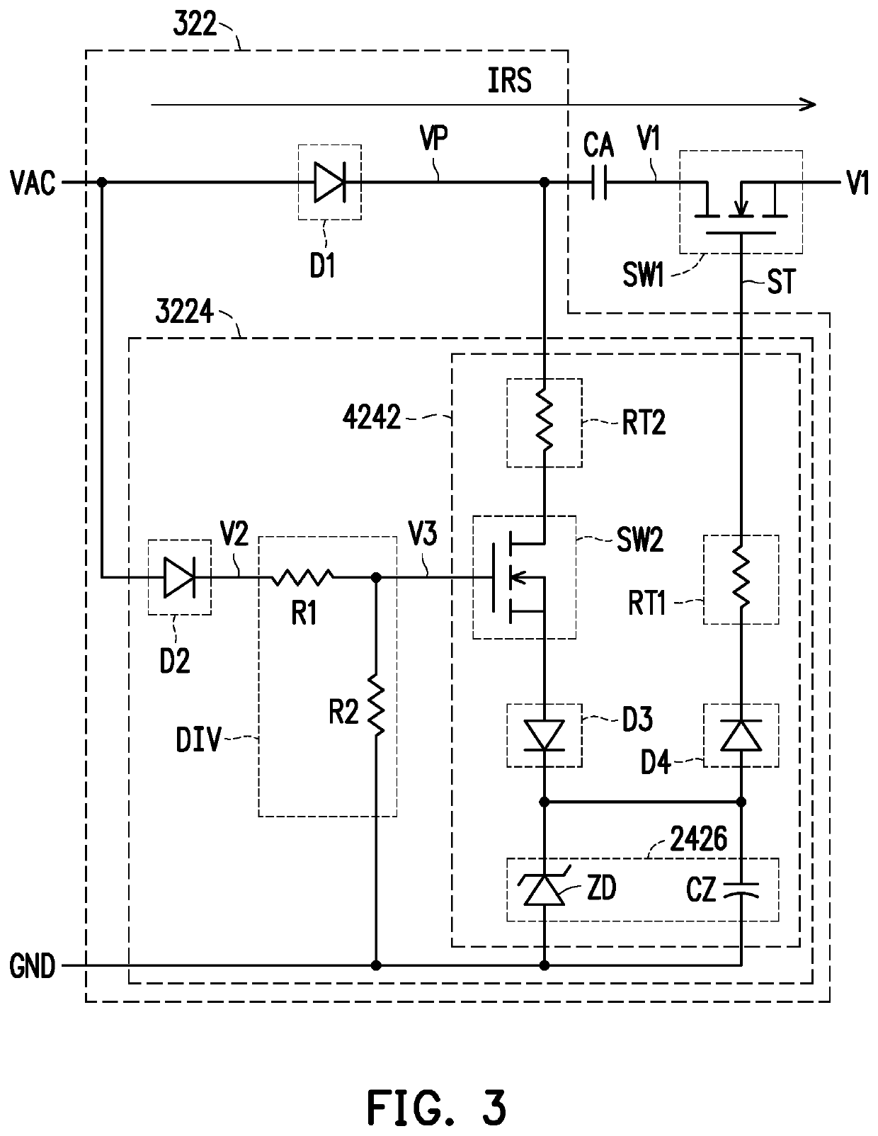
[0019]FIG. 1 is a circuit block diagram of a power supply apparatus 100 according to an embodiment of the present invention. Referring to FIG. 1, the power supply apparatus 100 may include, but is not limited to, a protection circuit 120 and a power conversion circuit 140. The protection circuit 120 may include a control circuit 122, an auxiliary capacitor CA, and a first switching circuit SW1. The control circuit 122 is configured to receive an AC voltage VAC from an AC power source PAC and generate a pulsating voltage VP and a control signal ST according to the AC voltage VAC. A first end of the auxiliary capacitor CA is coupled to the control circuit 122 to receive the ...


PUM


Abstract

A power supply apparatus including a protection circuit and a power conversion circuit is provided. The protection circuit includes a control circuit, an auxiliary capacitor, and a switching circuit. The control circuit receives an AC voltage from an AC power source and generates a pulsating voltage and a control signal accordingly. The auxiliary capacitor receives the pulsating voltage and provides a first voltage accordingly. The switching circuit is coupled to the auxiliary capacitor to receive the first voltage and coupled to the control circuit to receive the control signal. The switching circuit transmits the first voltage to the power conversion circuit in response to the control signal. The power conversion circuit converts the first voltage to an output voltage. When the switching circuit is switched to an on state in response to the control signal, the auxiliary capacitor reduces an input inrush current from the AC power source.

Description

CROSS-REFERENCE TO RELATED APPLICATION[0001]This application claims the priority benefit of Taiwan application serial no. 108114295, filed on Apr. 24, 2019. The entirety of the above-mentioned patent application is hereby incorporated by reference herein and made a part of this specification.BACKGROUND OF THE INVENTION1. Field of the Invention[0002]The present invention relates to a power supply technology, and in particular, to a power supply apparatus capable of reducing an input inrush current.2. Description of Related Art[0003]With the advancement of science and technology, various types of computer apparatuses have emerged. In order to boot the computer apparatuses successfully, power supply apparatuses play a very important role. In general, current computer apparatuses (such as gaming notebooks or desktop computers) typically have a number of peripheral interfaces to plug in various peripherals based on the needs of the application. In addition, each peripheral interface usua...

Claims


Application Information

Patent Timeline
Patent Type & Authority Patents(United States)
IPC IPC(8): H02H9/00G05F1/573H02H9/02H02H1/04
CPCH02H9/001G05F1/573H02H1/043H02H9/02H02H9/025
Inventor CHAN, TZU-TSENG
Owner ACER INC
Learn More