Exhaust gas treatment system

a technology of exhaust gas treatment and exhaust gas, which is applied in the direction of waste heat treatment, solid separation, inorganic chemistry, etc., can solve the problems of enormous steam consumption for regenerating absorbing liquid, and achieve the effects of reducing iron, reducing waste, and reducing iron

Active Publication Date: 2021-10-05
MITSUBISHI HEAVY IND ENG LTD
View PDF22 Cites 0 Cited by
  • Summary
  • Abstract
  • Description
  • Claims
  • Application Information

AI Technical Summary

Benefits of technology

[0020]According to the present invention, the iron-based solid substances being substances collected by the useful filter are recycled in the reduction device. With this, a waste amount disposed in the related art can be largely reduced. Further, the reduced iron can be obtained by subjecting the iron-based solid substances to the reduction process in the reduction device again. Thus, recycling efficiency can be improved.

Problems solved by technology

With the existing CO2 recovery device, a consumption amount of the steam for regenerating the absorbing liquid is enormous.
In addition, in a case where solid substances such as dust contained in the exhaust gas is accumulated in the absorbing liquid, when the solid substances are separated and removed from the absorbing liquid by, for example, a reclaimer, the following problems arise.

Method used


Image

  • Exhaust gas treatment system
  • Exhaust gas treatment system
  • Exhaust gas treatment system

Examples


first embodiment

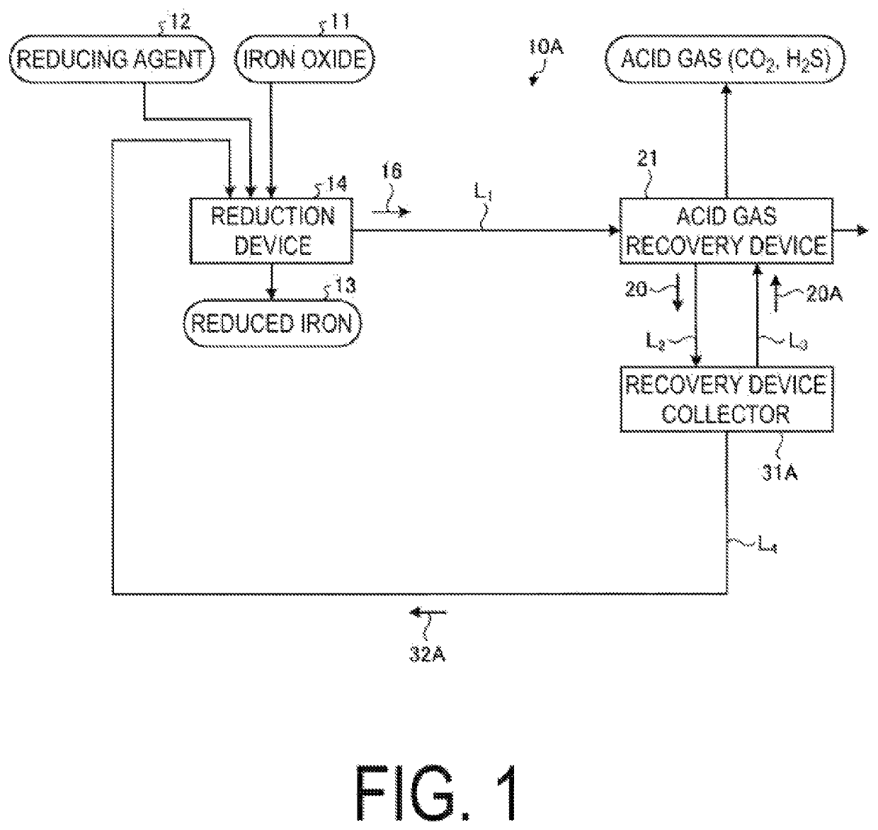
[0033]FIG. 1 is a schematic view of an exhaust gas treatment system for exhaust gas generated from a reduction device according to a first embodiment of the present invention. As illustrated in FIG. 1, an exhaust gas treatment system 10A according to this embodiment includes a reduction device 14, an acid gas recovery device 21, a recovery device collector 31A, and a first removed-substance returning line L4. The reduction device 14 is configured to perform a reduction process to turn iron oxide (for example, iron ore) 11 to reduced iron 13 by adding a reducing agent 12. The acid gas recovery device 21 is configured to recover CO2 being acid gas from exhaust gas 16 with CO2 absorbing liquid (hereinafter, referred to as “absorbing liquid”) 20 being acid gas absorbing liquid. The exhaust gas 16 is discharged from the reduction device 14 through an exhaust gas line L1, and contains at least powder-shaped iron-based solid substances 15 and acid gas (CO2). The recovery device collector 3...

second embodiment

[0053]In this embodiment, carbon dioxide (CO2) is exemplified as acid gas, and now description is made of a case of a carbon dioxide recovery device (hereinafter, referred to as “CO2 recovery device”) as an acid gas recovery device. FIG. 5 is a schematic view of a CO2 recovery device in a second embodiment of the present invention. As illustrated in FIG. 5, a CO2 recovery device 1000 in the second embodiment includes the reduction device 14, a CO2 absorbing tower (hereinafter, referred to as “absorbing tower”) 1004, an absorbing liquid regenerating tower (hereinafter, referred to as “regenerating tower”) 1006, a rich solution supply line L11, a lean solution supply line L12, the recovery device collector 31A, a liquid filtrate supply line L22, a desorption device, and a removed substance returning line L4. The reduction device 14 is configured to perform the reduction process to turn the iron oxide (for example, iron ore) 11 to reduced iron. The absorbing tower 1004 is configured to...


PUM

PropertyMeasurementUnit
temperatureaaaaaaaaaa
concentrationaaaaaaaaaa
magnetic fieldaaaaaaaaaa

Abstract

A reduction device, an acid gas recovery device, a recovery device collector, and a first removed substance returning line are provided. The reduction device is configured to perform a reduction process to turn iron oxide to reduced iron by adding a reducing agent. The acid gas recovery device is configured to recover CO2 being acid gas with CO2 absorbing liquid being acid gas absorbing liquid from exhaust gas containing at least powder-shaped iron-based solid substances and the acid gas, which are discharged from the reduction device. The recovery device collector is configured to collect the iron-based solid substance contained in the absorbing liquid with a filter. The iron-based solid substances collected by the recovery device collector are removed, and removed substances containing the removed iron-based solid substances are returned to the reduction device side through the first removed substance returning line.

Description

TECHNICAL FIELD[0001]The present invention relates to an exhaust gas treatment system.BACKGROUND ART[0002]For example, the following technology for removing and recovering CO2 is proposed. That is, when CO2 in exhaust gas generated through an iron manufacturing process and the like is recovered by a CO2 recovery device, for example, the exhaust gas is drawn in an absorbing tower, and is brought into contact with CO2 absorbing liquid (hereinafter, referred to as “absorbing liquid”) in the absorbing tower. In this manner, the absorbing liquid absorbs CO2 in the exhaust gas. The absorbing liquid having absorbed CO2 is sent to a regenerating tower, and is heated with steam. With this, CO2 is released, and CO2 having high purity is recovered.[0003]With the existing CO2 recovery device, a consumption amount of the steam for regenerating the absorbing liquid is enormous. Thus, in order to reduce the consumption amount of the steam, energy-saving measures further need to be taken. In additi...

Claims


Application Information

Patent Timeline
Patent Type & Authority Patents(United States)
IPC IPC(8): B01D53/14B01D35/06B01D53/96B01D37/02B01D53/62B01D47/06B03C1/00B01D53/78F27D17/00B01D53/22C01B32/50
CPCB01D53/1425B01D35/06B01D37/02B01D47/06B01D53/14B01D53/1475B01D53/228B01D53/62B01D53/78B01D53/96B03C1/00F27D17/00B01D2257/304B01D2257/504B01D2257/60B01D2258/025C01B32/50Y02C20/40Y02P10/25Y02P20/151Y02P70/10Y02P10/146C21B13/00C22B7/02
Inventor HIRATA, TAKUYATANAKA, HIROSHIKAMIJO, TAKASHIINUI, MASAYUKIKAWASAKI, SHIMPEI
Owner MITSUBISHI HEAVY IND ENG LTD
Why Eureka
Try Eureka