
Processes for adjusting at least one process condition of a chemical processing unit with a turbine

a technology of chemical processing unit and process condition, which is applied in the direction of steam engine plants, machines/engines, mechanical equipment, etc., can solve the problems of inefficiency in the process, energy loss, and increased operating cost of lost energy, so as to increase the amount of recovered power

Active Publication Date: 2021-09-28
UOP LLC
View PDF57 Cites 0 Cited by
  • Summary
  • Abstract
  • Description
  • Claims
  • Application Information

AI Technical Summary

Benefits of technology

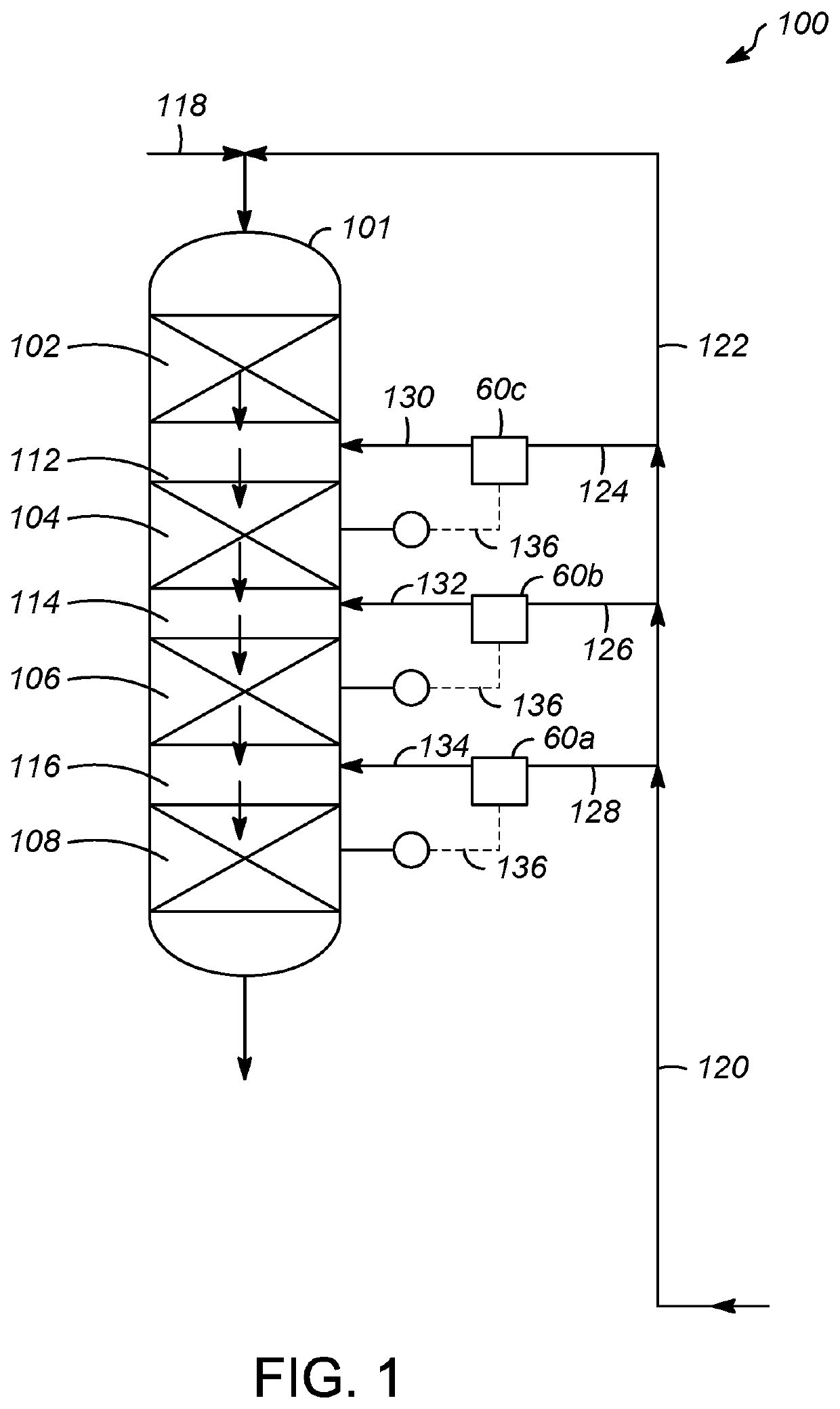
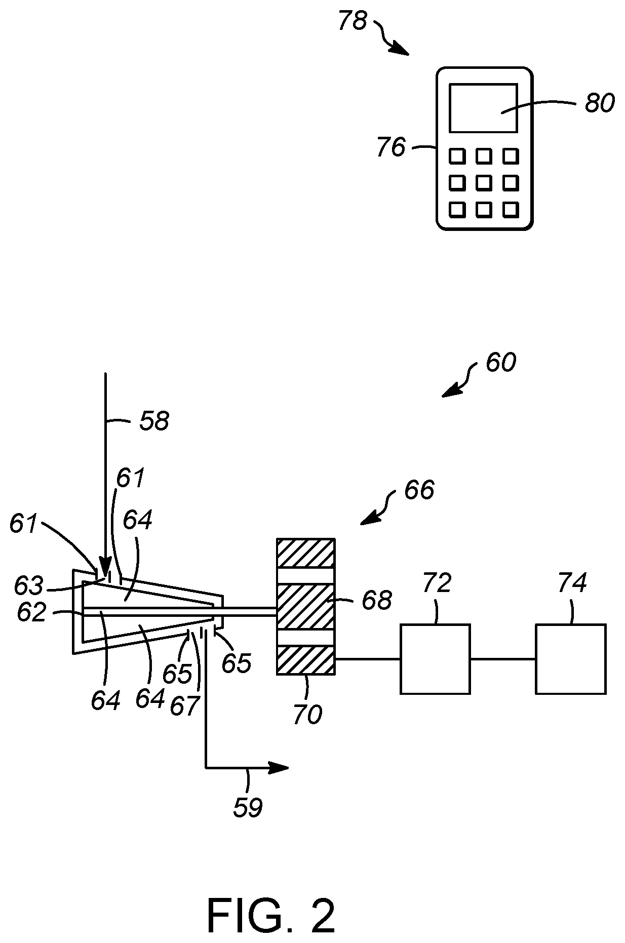
[0007]Using a turbine to control the flow stream without the assistance of a control valve can greatly increase the amount of recovered power (up to about 30% more) from the power recovery turbine and provide more cooling to the process stream which can often provide more process advantages. If slow control response of the turbine is an issue then limiting use of the turbine to slow responding or “loose” control point applications is more advantageous than in fast control systems where the turbine response is too sluggish. Flow control turbines using a variable nozzle turbine, inlet variable guide vanes, or changing the electromagnetic resistance to rotation via direct coupled variable electric load, to name a few, are used to modulate (or change) the resistance of the turbine, and increase or decrease the flow of fluid therethrough. The modulation should be applied to slow response or low required accuracy control loops like temperature, level, cascaded slave master control systems such as a distillation overhead flywheel control.

Problems solved by technology

Since the energy removed, via the pressure reduction, is dissipated without recovery by the control valve, the energy is lost.
Moreover, because the energy removed often is a result of energy added to the system, the lost energy can represent a higher operating cost.
This lost energy results in minimal temperature reduction versus the pressure reduction via an adiabatic pressure reduction across the control valve.
Thus, there is an inherent inefficiency in the process associated with supplying energy only to remove it without recovery.
However, since the costs of supply in the energy are relatively small in the overall process, refiners and processors often operate the processing / refining unit with this inefficiency to maintain throughput of the processing / refining unit.
Nevertheless, this inefficiency is an opportunity for processors to lower operating costs and, thus increase profits.
However, unlike the control valves, the turbines convert the removed energy into electrical energy to be utilized elsewhere.

Method used


Image

  • Processes for adjusting at least one process condition of a chemical processing unit with a turbine
  • Processes for adjusting at least one process condition of a chemical processing unit with a turbine

Examples


specific embodiments

[0037]While the following is described in conjunction with specific embodiments, it will be understood that this description is intended to illustrate and not limit the scope of the preceding description and the appended claims.

[0038]A first embodiment of the invention is a process for controlling at least one steady process condition of a chemical processing unit, the process comprising passing a fluid through a turbine in order to provide the fluid with a flow associated with at least one process condition of a chemical processing unit; rotating a turbine wheel within the turbine, the turbine wheel configured to transmit rotational movement to an electrical generator; generating electricity with the turbine; and, modulating a resistance of the turbine in order to adjust the flow of the fluid through the turbine, wherein a response time of at least one steady state process condition to a new steady state process condition of at least 10% difference is at least one second to reach 5...


PUM


Abstract

Processes for controlling at least one process condition of a chemical processing unit with a turbine. In the processes, a flow of a fluid is adjusted with a turbine in order to provide the fluid with a flow associated with at least one process condition of a chemical processing unit. The turbine wheel is rotated within the turbine, and the turbine wheel is configured to transmit rotational movement to an electrical generator. The resistance of the turbine is modulated and adjusts the flow of the fluid through the turbine. A response time of at least one steady state process condition to a new steady state process condition of at least 10% difference is at least one second to reach 50% of the difference between the at least one steady state process condition and the new steady state process condition after modulating the resistance of the turbine.

Description

FIELD OF THE INVENTION[0001]This invention relates generally to processes for adjusting a process condition, and more particularly to processes wherein a steady state process condition is adjusted with a turbine, and more specifically by modulating a resistance of the turbine.BACKGROUND OF THE INVENTION[0002]Chemical refining and processing methods frequently involve gaseous or vapor streams that are passed through control valves. The control valves are used to lower the pressure of the gaseous streams to provide the gaseous stream with a desired characteristic, for example, pressure, temperature, etc. In the control valve, mechanical energy is dissipated to decrease the flow rate and pressure. Since the energy removed, via the pressure reduction, is dissipated without recovery by the control valve, the energy is lost.[0003]Moreover, because the energy removed often is a result of energy added to the system, the lost energy can represent a higher operating cost. This lost energy res...

Claims


Application Information

Patent Timeline
Patent Type & Authority Patents(United States)
IPC IPC(8): F01K23/06F01D17/16F01D15/10F01D21/14
CPCF01K23/064F01D15/10F01D17/16F01D21/14F05D2220/31F05D2220/62F05D2220/76F05D2270/052F05D2270/62F05D2220/722C10G49/26C10G11/187Y02E20/18
Inventor FREY, STANLEY JOSEPHHARRIS, JAMES W.
Owner UOP LLC
Learn More