


Quick Research
Generate reliable direction feasibility study reports for your R&D in just a few steps.

Technical Q&A
Discover and master advanced knowledge NOW. Basics, ideas, possibilities, all at once.

Find Solutions
As an expert in R&D theories, this can generate solutions to your technical problems instantly.

Evaluate Feasibility
Analyze your overall solution with one click, know your potential R&D risks in advance.

Monitor Landscape
Get weekly tech updates, stay abreast of the latest tech innovations and key insights.
Instrument for measuring pressure-induced sensory threshold with non-electrical power assist pivot mechanism
a technology of sensory threshold and pivot mechanism, which is applied in the field of sensory testing devices, can solve the problems of adding time to the testing procedure, false detection, and time-consuming tests, and achieves the effects of quick and accurate positioning, rapid use, and storag
- Summary
- Abstract
- Description
- Claims
- Application Information
AI Technical Summary
Benefits of technology
Problems solved by technology
Method used
Image


Examples
first embodiment
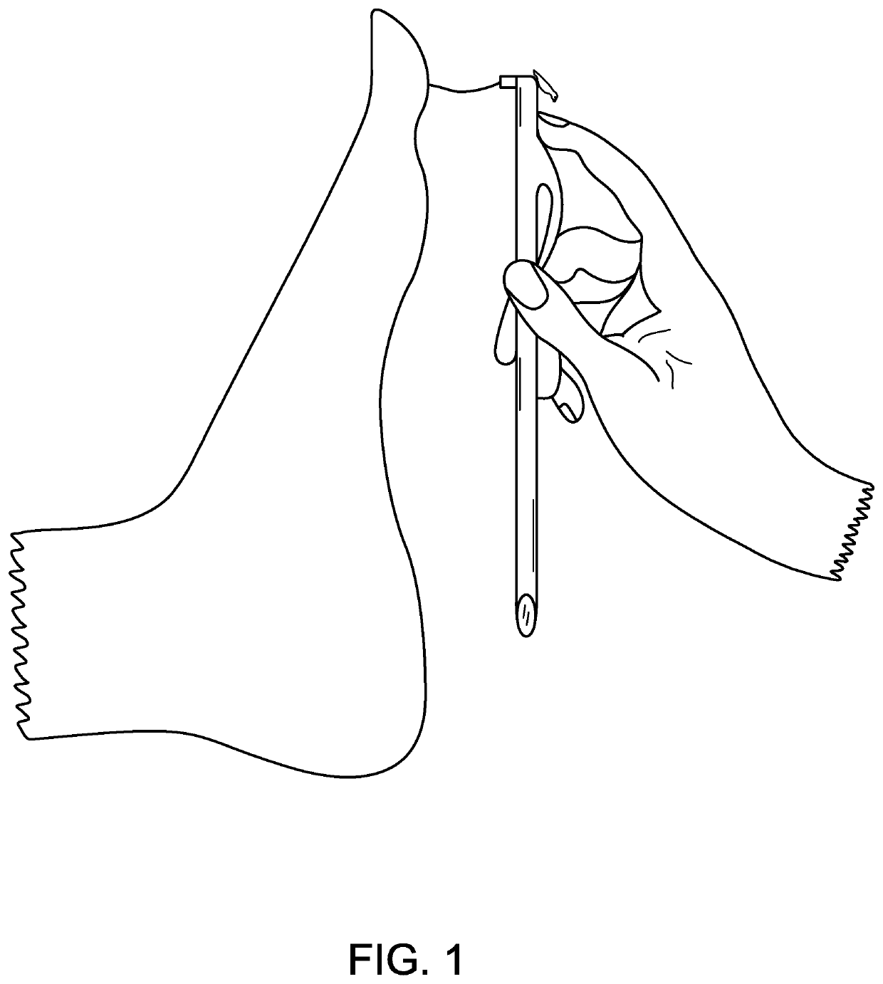
[0059]FIG. 1 shows the overall appearance of a first embodiment in open, testing position as it is used to test the sensation of a body surface.
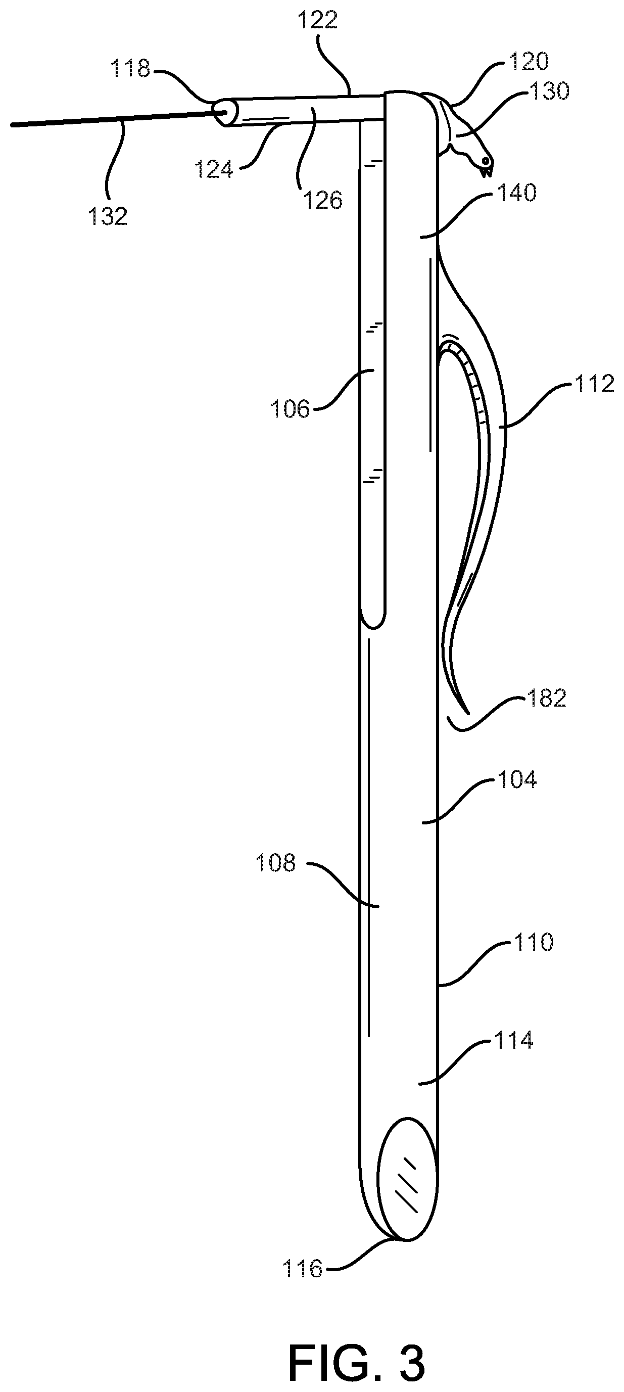
[0060]FIG. 2 is a ventral lateral perspective view of the first embodiment in open, testing position. The embodiment is composed of a handle member 100 and a pivotally attached head member 102. An elongated body 104 of the handle member 100 has an elongated channel 106 on a ventral, belly surface 108 toward a distal end 140 of the handle member 100. A channel lip 360 as shown in FIG. 32 is a variation. FIG. 3 is a lateral perspective view that shows a dorsal, back surface 110 of the handle member 100 that has a pocket clip 112 which is similar to (like) one on a retractable ballpoint pen. At a proximal end 114 of the handle member 100, there is a tapered beveled scrape tip 116.
[0061]The head member 102 is oriented with a proximal end 118, a distal end 120, a ventral, belly surface 122, and a dorsal, back surface 124. The head member 102 (als...
second embodiment figs.19
Second Embodiment FIGS. 19A, 19B, 19C
[0127]FIG. 19A shows a lateral middle sectional view of a second embodiment in closed, storage position. This embodiment uses a leaf / flat spring 228 axially aligned with a handle member 230. The distal end of the leaf spring 228 contacts a storage position contact surface 232 of a body 234 of head member 236 in a parallel manner when the spring 228 is in fully relaxed resting position. When a head member 236 is pivoted around a pivot moment 238 of head member into the open, testing position, a bias corner 240 flexes the leaf spring 228 as seen in FIG. 19B. Once the head member 236 is pivoted into the full open, testing position the leaf spring 228 once again rests in a fully relaxed position in parallel contact with a testing position contact surface 242 of head member 236 as shown in FIG. 19C. In this leaf spring embodiment, the closed, storage state dorsal surface of a filament arm 244 has a recess 246 so there is no interference between the le...
third embodiment figs.20a , 20b , 21
Third Embodiment FIGS. 20A, 20B, 21
[0129]FIG. 20A shows a lateral middle sectional view of a third embodiment in closed, storage position. This embodiment uses magnetic forces to power assist the pivot of a head member 254 upon a distal end of a handle member 256, A head member bar magnet 258 opposes a handle member bar magnet 260 aligned in mating polarity. One of these two magnets, such as the longer one, may be replaced by a section of ferromagnetic material that is attracted to the opposing magnetic without producing its own magnetic field. FIG. 20B shows a lateral middle sectional partial view of the third embodiment in open functional, testing position. The length of the head member bar magnet 258 is longer than the handle member bar magnet 260. The length differential is such that the full length of the ventral surface of the handle member bar magnet 260 is in contact with a portion of the head member bar magnet 258 while in closed, storage position and the full distal surfac...
PUM
 Abstract
Description
Claims
Application Information
 - R&D Engineer
- R&D Manager
- IP Professional
- Industry Leading Data Capabilities
- Powerful AI technology
- Patent DNA Extraction
Browse by: Latest US Patents, China's latest patents, Technical Efficacy Thesaurus, Application Domain, Technology Topic, Popular Technical Reports.
© 2024 PatSnap. All rights reserved.Legal|Privacy policy|Modern Slavery Act Transparency Statement|Sitemap|About US| Contact US: help@patsnap.com