
Check valve assembly

a technology for checking valves and assembly parts, applied in the direction of valve housings, tomography, operating means/releasing devices, etc., can solve problems such as creating false positives, and achieve the effect of reducing the possibility of saline and contrast undetected mixing, preventing, or reducing the possibility of saline and contrast mixing, and simple and effective check valve assembly

Active Publication Date: 2021-09-21
ILLINOIS TOOL WORKS INC
View PDF40 Cites 0 Cited by
  • Summary
  • Abstract
  • Description
  • Claims
  • Application Information

AI Technical Summary

Benefits of technology

The patent is about a need for a check valve assembly that prevented the mixing of saline and contrast, reducing the possibility of image false positives caused by spots from contrast agent. The goal is to create a simpler and more effective check valve assembly.

Problems solved by technology

For example, the contrast may form spots on a scanned image, thereby creating a false positive.

Method used


Image

  • Check valve assembly
  • Check valve assembly
  • Check valve assembly

Examples


Embodiment Construction

[0002]Embodiments of the present disclosure generally relate to a check valve assembly, and, more particularly, to a check valve assembly that may be configured for medical applications, such as for use with computed tomography (CT) imaging.

BACKGROUND

[0003]During certain types of medical imaging (such as during computed tomography imaging), contrast agent may be used. For example, an individual may ingest or be injected with contrast agent before the imaging process. When the individual is being imaged, the contrast agent allows for more defined imaging results.

[0004]During an imaging session, saline and contrast merge within a connection joint that connects to a syringe through a conduit. A check valve is typically positioned within each of a saline line and a contrast line. For example, the saline line includes a first check valve, and the contrast line includes a separate and distinct second check valve. The check valves are separated from the connection joint. Because the check ...


PUM


Abstract

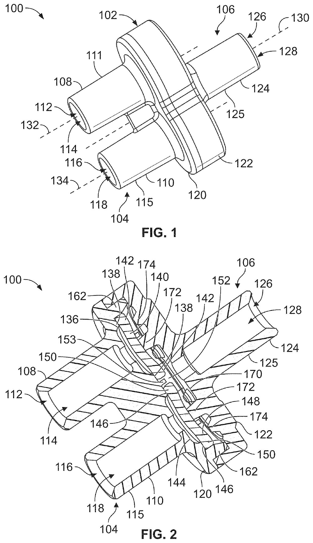
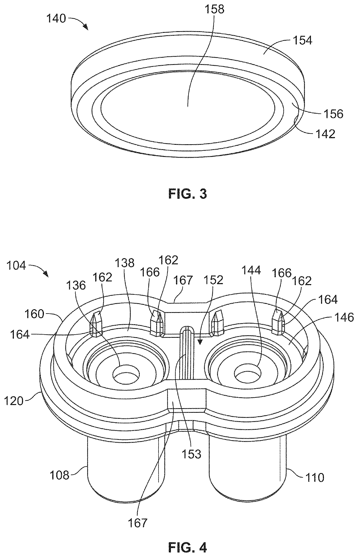
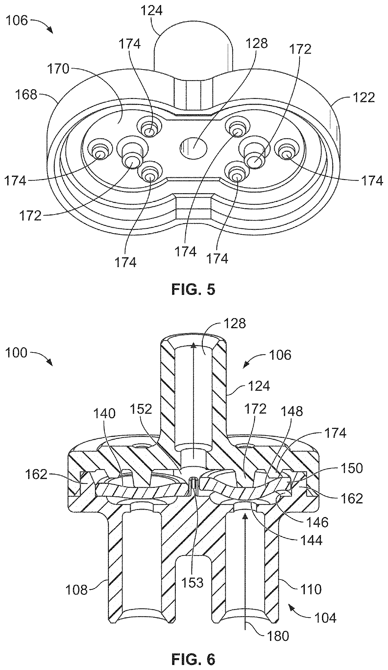
An infusion set check valve assembly includes a self-contained housing that defines inlet ports and an outlet port. The assembly also includes at least one check valve disposed within the self-contained housing between the outlet channel and at least one of the inlet ports. The at least one check valve is configured to open for a first fluid to flow from a first inlet to a patient line via an outlet channel while a second fluid also flows from a second inlet to the patient line via the outlet channel. The at least one check valve closes to prevent the first fluid from flowing to the patient line via the outlet channel while the second fluid flows to the patient line.

Description

CROSS-REFERENCE TO RELATED APPLICATIONS[0001]This application is a continuation-in-part of U.S. patent application Ser. No. 15 / 762,639, filed 23 Mar. 2018, which is a national stage application of 35 U.S.C. § 371(c) of PCT application serial number PCT / US2016 / 048839, filed 26 Aug. 2016, which claims priority to U.S. Provisional Application No. 62 / 238,203, filed 7 Oct. 2015. The entire disclosures of these applications are incorporated herein by reference.FIELD OF EMBODIMENTS OF THE DISCLOSURE[0002]Embodiments of the present disclosure generally relate to a check valve assembly, and, more particularly, to a check valve assembly that may be configured for medical applications, such as for use with computed tomography (CT) imaging.BACKGROUND[0003]During certain types of medical imaging (such as during computed tomography imaging), contrast agent may be used. For example, an individual may ingest or be injected with contrast agent before the imaging process. When the individual is being...

Claims


Application Information

Patent Timeline
Patent Type & Authority Patents(United States)
IPC IPC(8): F16K31/126F16K27/02F16K15/02A61M39/24
CPCF16K31/1268A61M39/24F16K15/023F16K27/0236A61M2039/2433Y10T137/7838A61M2039/1083A61M2039/1088A61M2039/2446A61M2039/2453A61M2039/246A61M2039/2466A61B6/032A61B6/481A61M5/007A61M5/19A61M2005/1787F16K15/141
Inventor CARMODY, COLM M.HENN, GERARD G.SCHASER, ROBERT R.JOZWIK, RAYMONDTHOMPSON, DAVID DRAKELEONHARD, MICHAEL GRANTCASEY, BRENDANSIDDHARTHA, YASHO CONNOR, ELIZABETH
Owner ILLINOIS TOOL WORKS INC
Learn More