Plasma confinement device with helical current and fluid flow

a technology of helical current and magnetic confinement, which is applied in the direction of nuclear engineering, nuclear reactor reduction, greenhouse gas reduction, etc., can solve the problems of limited cusped-field reactors not reaching adequate, and no means of this have been available. achieve the effect of reducing particle losses

Active Publication Date: 2021-08-31
PRATER DANIEL
View PDF8 Cites 2 Cited by
  • Summary
  • Abstract
  • Description
  • Claims
  • Application Information

AI Technical Summary

Benefits of technology

[0009]A device and method for creating plasma conditions [1] sufficient for deuterium-tritium and advanced, fuel thermonuclear fusion consists of an inner helicity-containing plasma such as a spheromak compact toroid plasmoid bounded by a plurality of outer cusped magnetic fields. Helicity driven by helicity injectors energizes the plasmoid with helical current. The device further includes means for driving fluid rotation about the device axis, means for driving fluid rotation about the magnetic axis, and means for a hot electron sheath. Driving fluid rotation about both the magnetic and geometric axes is helical fluid flow. Means are also provided for reducing particle losses out through the open cusp field lines through helicity injector rectification.

Problems solved by technology

Ideal MHD-stable confinement geometries do exist and they are open cusped-field confinement configurations subject to plasma losses.
Excessive free-streaming plasma losses out through the open cusp regions has limited cusped-field reactors from attaining adequate temperatures and pressures for thermonuclear fusion [4].
Driven, flow can accomplish these improvements in transport barrier function with the additional benefit of control of flow speed, however, no means of this have yet been available.

Method used


Image

  • Plasma confinement device with helical current and fluid flow
  • Plasma confinement device with helical current and fluid flow
  • Plasma confinement device with helical current and fluid flow

Examples


Embodiment Construction

[0021]The present invention will now be described to provide an overall understanding of the principles of the structure, function, manufacture, and use of the devices and methods disclosed herein. Those skilled in the art will understand that the devices and methods specifically described herein and illustrated in, the accompanying drawings are non-limiting forms and that the scope of the present invention is defined solely by the claims. The features illustrated and / or described in connection with a form may be combined with the features of other forms. Such modifications and variations are intended to be included within the scope of the present invention, but not limiting thereof.

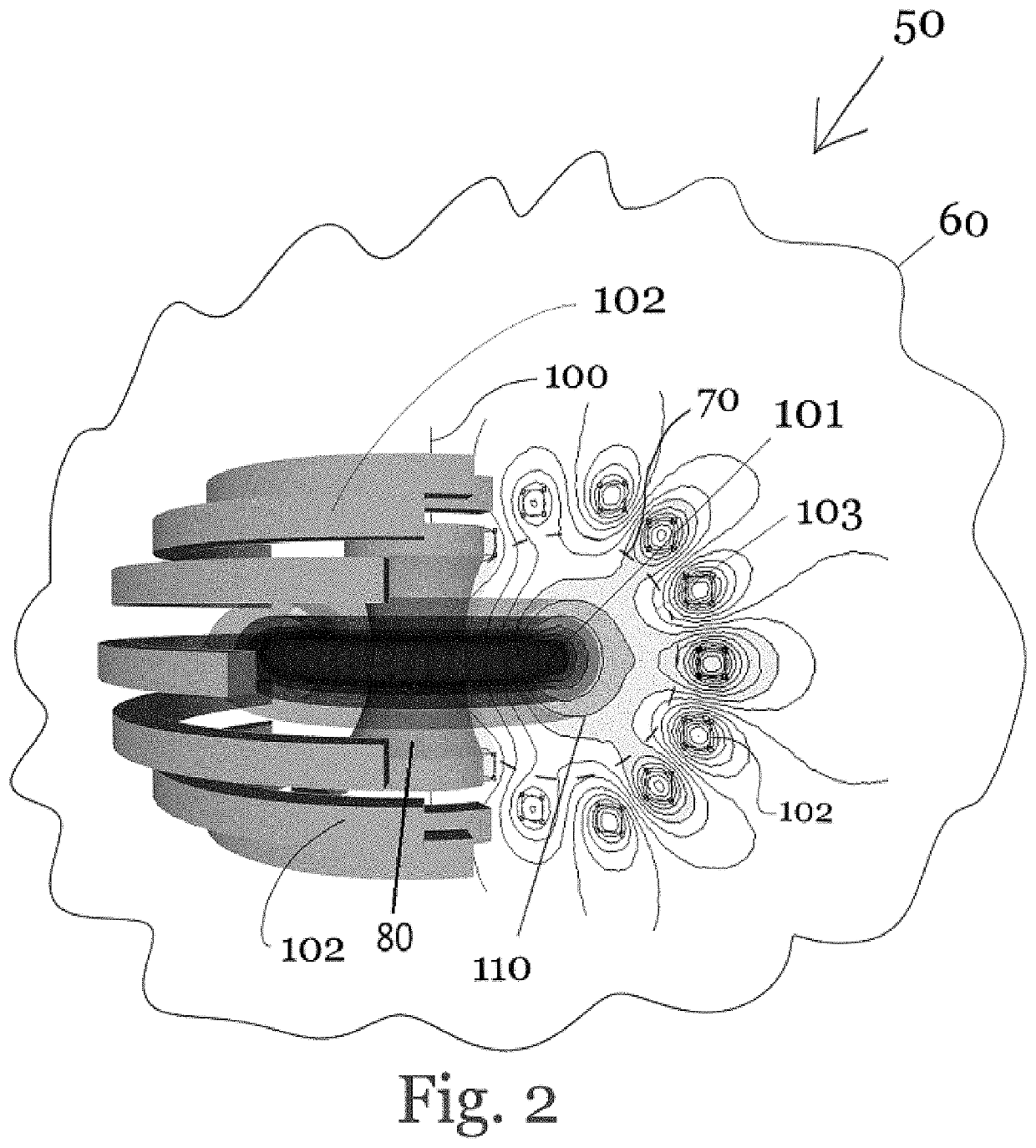
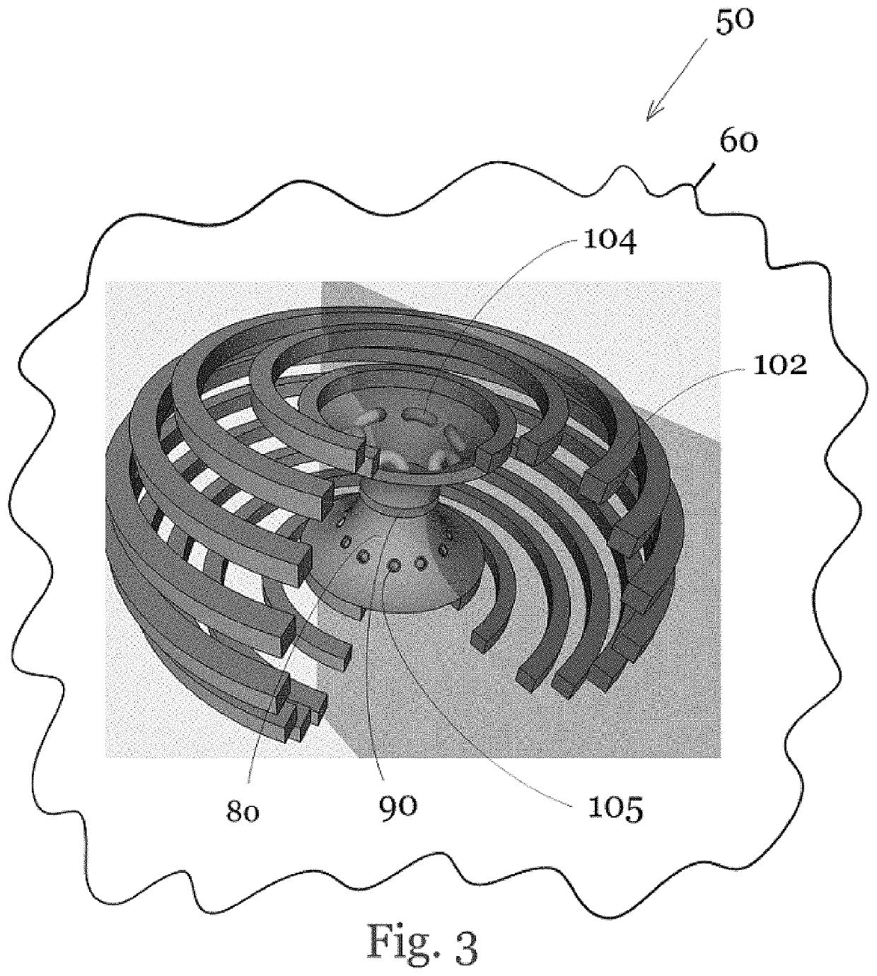
[0022]FIGS. 1-3, 5, and 7-8 show a multiple magnetic cusp plasma confinement system, device or reactor 50 having closed internal plasma toroidal and poloidal fields 101 arising from helicity injection, for example by, steady-inductive helicity injection (SIHI) via SIHI injectors 104 with the openings of ...


PUM


Abstract

A device and method for generating plasma conditions for deuterium-tritium and advanced fuel thermonuclear fusion consisting of an inner helicity-containing plasma such as a spheromak compact toroid bounded by a plurality of outer cusped magnetic fields. Helicity driven by steady-inductive helicity injectors energizes the plasmoid with helicity. The device further includes means for driving fluid rotation about the device axis, about the device magnetic axis, and means for a hot electron sheath. Means are also provided for reducing particle losses out through the open cusp field lines through helicity injector rectification.

Description

CROSS-REFERENCE TO RELATED APPLICATIONS[0001]This U.S. non-provisional patent application claims the benefit of and / or priority under 35 U.S.C. § 119(e) to U.S. provisional patent application Ser. No. 62 / 795,003 filed Jan. 21, 2019 titled “Plasma Confinement Device,” the entire contents of which is specifically incorporated herein by reference.FIELD OF THE INVENTION[0002]The present invention relates in general to the subjects of ionized gas (plasma) devices, and devices and methods for plasma heating and specifically, to devices and methods for plasma heating and current drive in magnetic confinement devices possessing cusp-shaped magnetic fields.BACKGROUND OF THE INVENTION[0003]Confining and heating plasma for thermonuclear fusion and other uses requires plasma pressure to exceed a threshold measured typically in terms of plasma temperature and density for some minimum of plasma energy confinement time [1].[0004]A primary reason why thermonuclear fusion energy is not yet in wide-s...

Claims


Application Information

Patent Timeline
Patent Type & Authority Patents(United States)
IPC IPC(8): G21B1/05G21B1/11H05H1/10
CPCG21B1/05G21B1/11H05H1/10G21B1/057Y02E30/10
Inventor PRATER, DANIEL
Owner PRATER DANIEL
Why Eureka
Try Eureka