Removing mechanism of storage device

a technology of storage device and mechanism, which is applied in the direction of recording information storage, record carrier construction details, instruments, etc., can solve the problems of extending the size of rack or cabinet, and inconvenience of dismounting hard drives

Active Publication Date: 2021-08-17
STORAGE RECOVERY MIGRATION SERVICES LTD
View PDF4 Cites 0 Cited by
  • Summary
  • Abstract
  • Description
  • Claims
  • Application Information

AI Technical Summary

Benefits of technology

[0005]An objective of the present application is to provide a removing mechanism of storage device. A top plate and a bottom plate sandwich a control handle and a sliding plate and the control handle controls the sliding plate to slide between the top plate and the bottom plate for driving a block member of the bottom plate extended from a sliding recess of the top plate. Then the storage device on the top plate can be dismounted rapidly and thus providing convenience in dismounting storage devices.
[0006]The present application discloses a removing mechanism of storage device, which comprises a top plate, a bottom plate, a sliding plate, and a control handle. The top plate includes a sliding recess on a first side and a fixing side plate on a second side and a third side, respectively. The fixing side plate includes a plurality of fixing members for fixing the storage device on the top plate. Furthermore, the top plate includes a plurality of extending members below for hanging the bottom plate and enabling the bottom plate to slide below the top plate. The bottom plate includes a plurality of first openings and a second opening between the plurality of first openings. The plurality of first openings enable the plurality of extending members to slide and hang the bottom plate. The sliding plate is disposed slidably between the top plate and the bottom plate. The sliding plate includes a first block member on a first side. The first block member is disposed slidably in the sliding recess. The sliding plate includes a pivot member on a second side. The pivot member is disposed slidably in the second opening and includes a third opening for pivoting the control handle. In addition, the first side of the control handle is connected pivotally between the top plate and the bottom plate. A fourth side of the control handle extends to the top plate and outside a fourth side of the bottom plate, so that the control handle can control the sliding of the sliding plate. Thereby, the first block member is driven to slide in the sliding recess for dismounting the storage device on the top plate rapidly.

Problems solved by technology

Unfortunately, to rotate the handle as described above, certain operating space is required, resulting in the concern of extending of the size of rack or cabinet and inconvenience of dismounting hard drives.

Method used


Image

  • Removing mechanism of storage device
  • Removing mechanism of storage device
  • Removing mechanism of storage device

Examples


Embodiment Construction

[0024]In order to make the structure and characteristics as well as the effectiveness of the present application to be further understood and recognized, the detailed description of the present application is provided as follows along with embodiments and accompanying figures.

[0025]Considering that it is difficult to dismount storage devices using the removing mechanism according to the prior art, the present application provides a removing mechanism of storage device for solving the space and volume problems according to the prior art.

[0026]In the following, the properties and the corresponding structure of the removing mechanism of storage device disclosed in the present application will be further described.

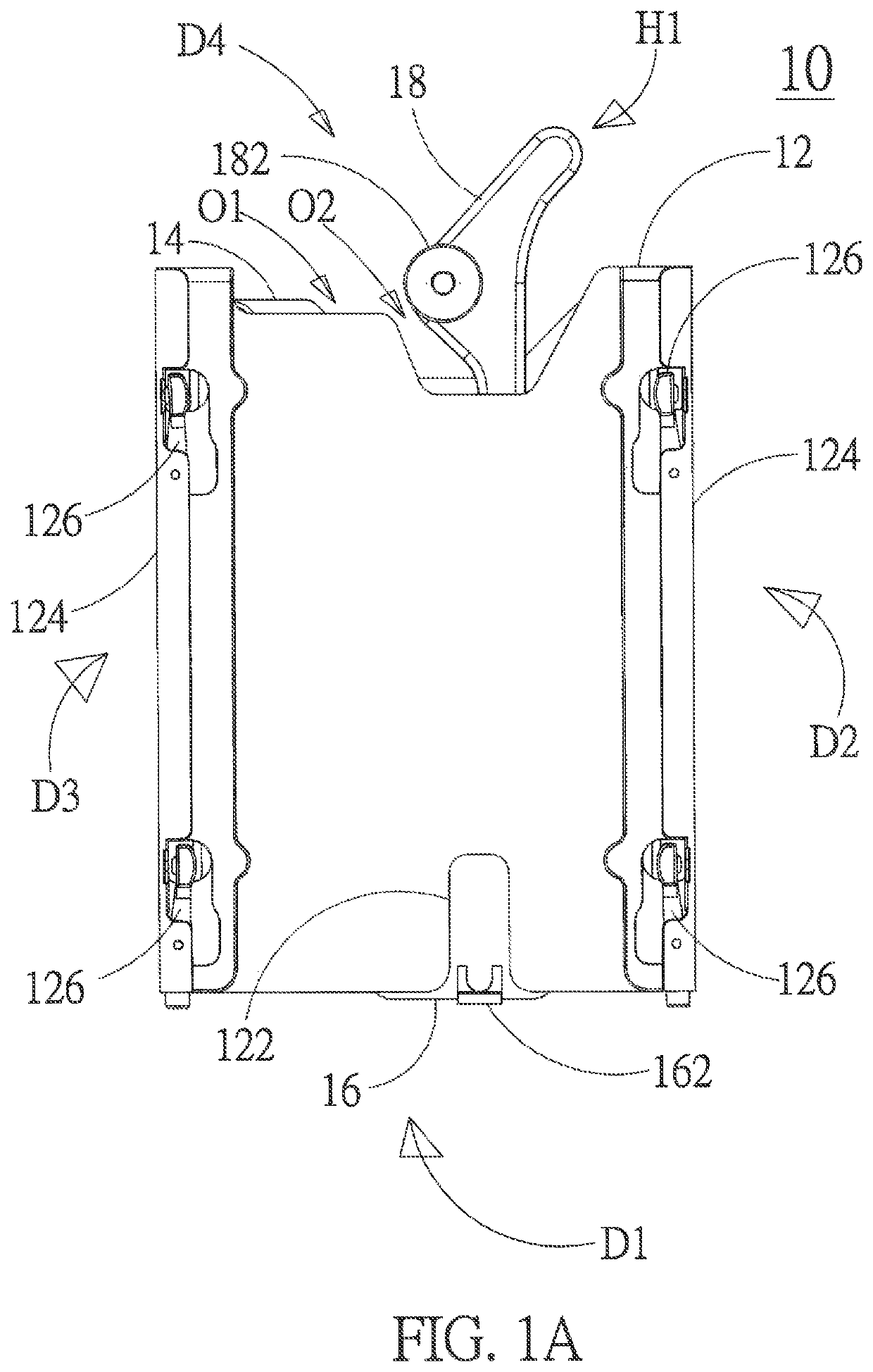
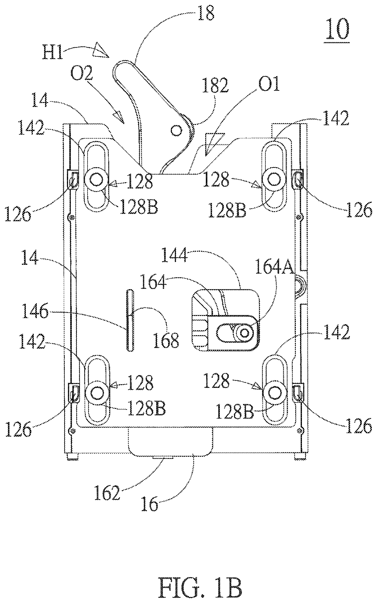
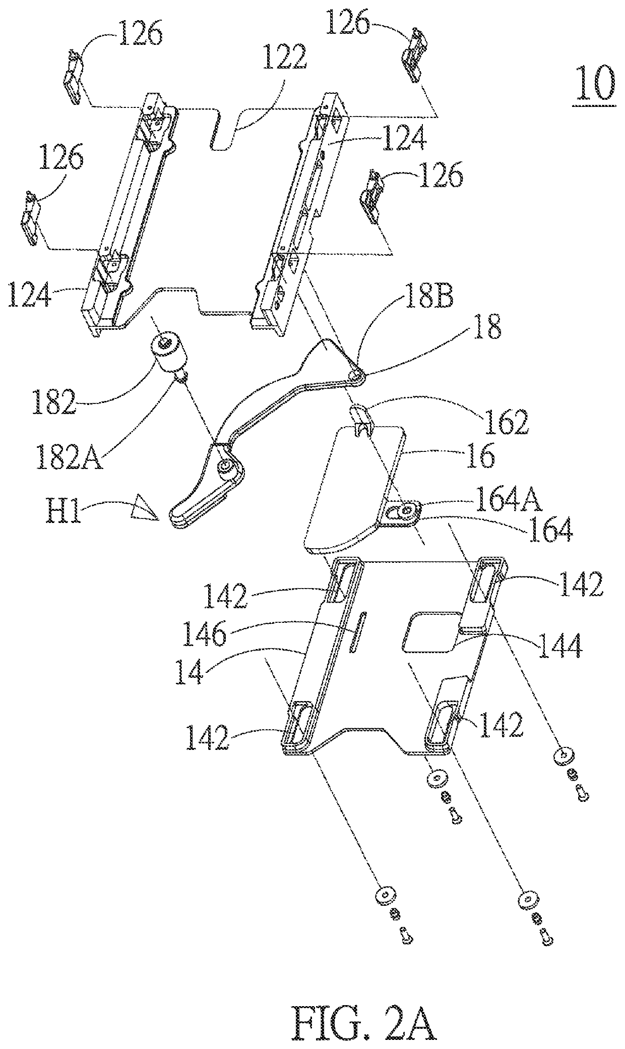
[0027]Firstly, please refer to FIG. 1A to FIG. 2B, in which the figures show a top view, a bottom view, an exploded view, and another an exploded view according to an embodiment of the present application. As shown in the figures, the removing mechanism 10 of storage device ac...


PUM

PropertyMeasurementUnit
elasticaaaaaaaaaa
sizeaaaaaaaaaa
volumeaaaaaaaaaa

Abstract

A removable mechanism for a hard drive is revealed. The removable mechanism includes an upper substrate and a base plate hanged and sliding below the upper substrate, and a control handle and a sliding board are set between the upper substrate and the base plate to carry each other. The control handle controls a pivot element sliding on an opening of the base plate. By carrying each other to carry a stop element of the base plate, the stop element slides on a concave opening for dismounting a storage device inserted to the removable drawing mechanism. Thereby, the present application is convenient for dismounting the storage device.

Description

FIELD OF THE INVENTION[0001]The present application relates generally to a removing device, and particularly to a removing mechanism of storage device.BACKGROUND OF THE INVENTION[0002]Generally, a cloud system usually provides cloud storage space for storing data or files of customers according to their subscription, in particular for applications of distributed computing systems. For example, clouding computing becomes more popular in consumer and enterprise data storage. The so-called cloud data storage adopts massive network storage servers. By serially connecting a plurality of hard disk drives or a plurality of solid-state drives, a unified repository, central processing units, banks, or arrays are organized and deployed. Typically, the plurality of servers are disposed for the purpose of large-scale operations. For example, a single cloud data storage system can include thousands or tens of thousands of storage servers installed in stacks or in rack-mounted arrays. Thereby, th...

Claims


Application Information

Patent Timeline
Patent Type & Authority Patents(United States)
IPC IPC(8): G11B33/12H05K7/14G11B17/04G11B33/04
CPCG11B33/124G11B17/0407G11B33/04H05K7/1415H05K7/1488G11B33/128
Inventor WU, YOU-LUNWING, KENNETH DONALD
Owner STORAGE RECOVERY MIGRATION SERVICES LTD
Why Eureka
Try Eureka