Laser processing head and laser processing system including the same

Active Publication Date: 2021-08-03
PRECITEC GMBH
View PDF6 Cites 1 Cited by
  • Summary
  • Abstract
  • Description
  • Claims
  • Application Information

AI Technical Summary

Benefits of technology

The present invention aims to improve the sealing of a laser processing head against dirt particles, which can damage optical components and limit their lifespan. The invention achieves this by providing an access opening on the mounting surface, which is the least exposed to dirt particles, reducing the amount of dirt particles that enter the housing via the access opening. The design also allows for easy and safe access to the optical components for service and replacement. The optical components of the laser processing head may include focusing optics、 lenses, and protective windows. The access cover connected to the optical components simplifies the exchange of optical components. The mounting surface may include alignment means and fixing means for aligning and fixing the laser processing head to the carrier. The mounting cover may have a frame shape for weight reduction and may include fixing means to mount the laser processing head on the carrier.

Problems solved by technology

However, still a considerable amount of dirt particles can enter the housing via the access openings, causing undesired thermal effects and reducing a lifetime of optical components.
Moreover, for changing the optical components, it is normally not possible to remove only the optical component, but a larger unit must be removed from the housing.
However, the interfaces of the modules 10a, 10b, 10c, 10d and the access openings or access covers are heavily soiled by dust, smoke, splashes and the like.
Yet, a perfect cleaning seems to be impossible.
Thus, even when access covers or sealings are provided at the interfaces or access openings, the housing is not fully protected from introduction of dirt particles.
Moreover, since the access to the optical components is typically provided on exposed surfaces of the housing, the user often feels invited to directly open the housing in the dirty environment of the laser processing system.
Also, it is not intuitive which optical components should be accessed by the user, and which optical components should only be accessed by an experienced service engineer.
This may lead to unintentional opening of the laser processing head, with drastic consequences.
Further, due to the many interfaces between the modules and access openings or covers which are visible in the mounted state of the laser processing head, only few areas are available for customized design.
The concept of current laser processing heads is still based on the design of CO2 laser processing heads, where simple, front-side or lateral-side access to the optical components was uncritical and practical.
However, laser processing heads using lasers with a wavelength in the range of 400 to 2000 nm are very sensitive for soiled optical components, since this laser wavelength range corresponds to the range of sizes of typical dirt particles.
Thus, in times of high-performance fiber lasers, this design of front / lateral-side access is no longer up to date.

Method used


Image

  • Laser processing head and laser processing system including the same
  • Laser processing head and laser processing system including the same
  • Laser processing head and laser processing system including the same

Examples


Embodiment Construction

[0043]Throughout this disclosure, same elements are denoted with the same reference signs.

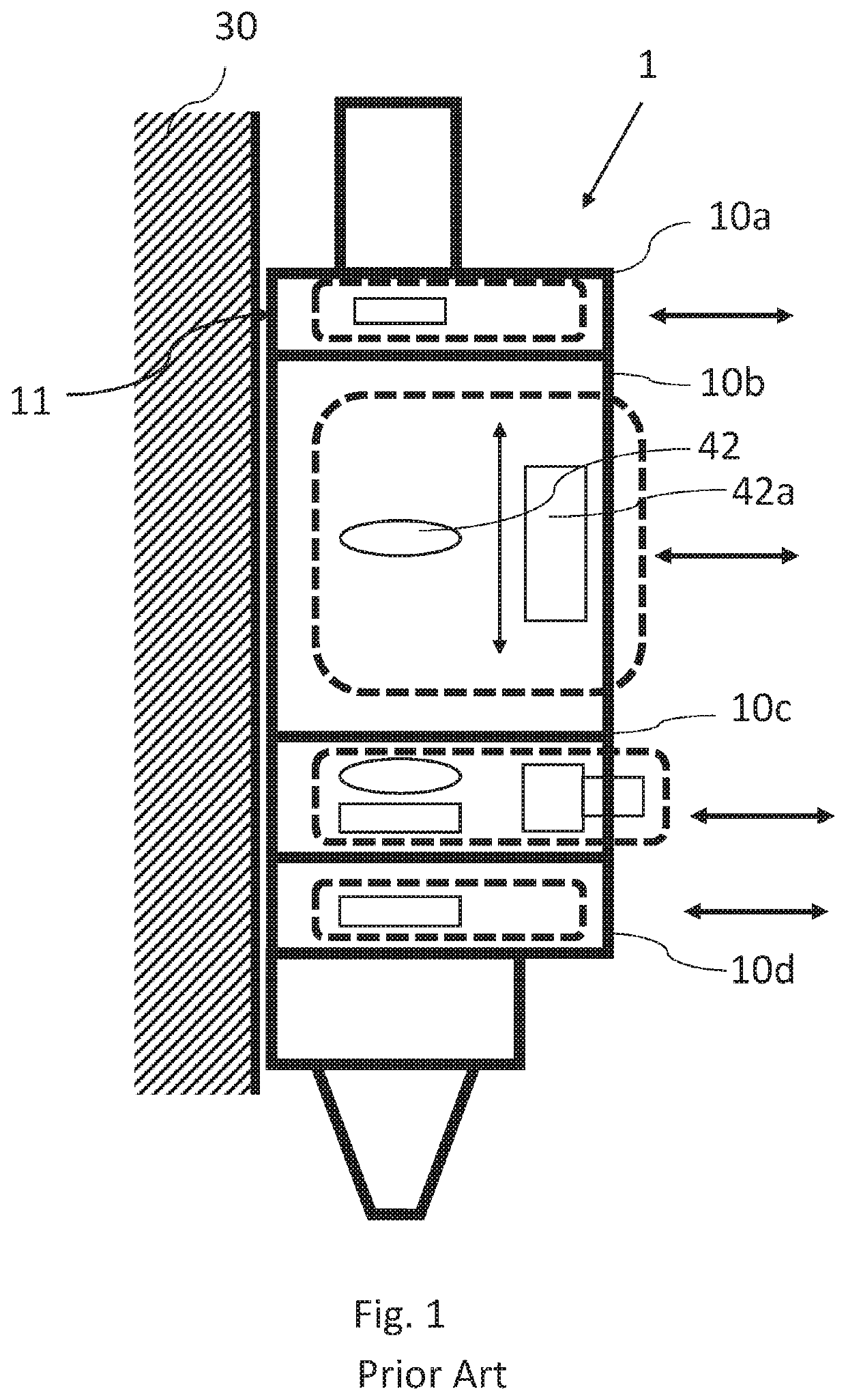
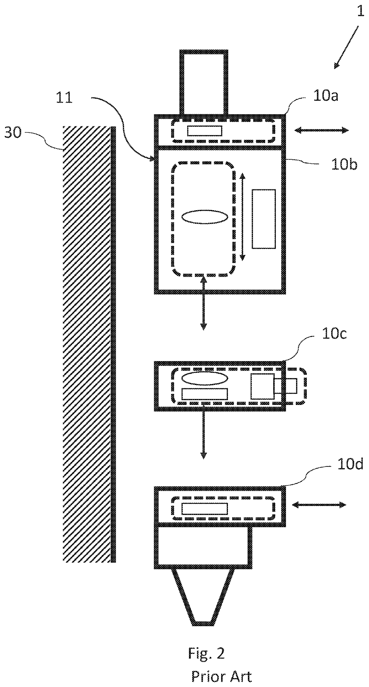
[0044]Generally, a laser processing head 1 is mounted to a carrier 30 of a laser processing system at a mounting surface 11 of a housing 10 of the laser processing head 1. In the related art, the mounting surface 11 has almost no other functions besides this mounting function.

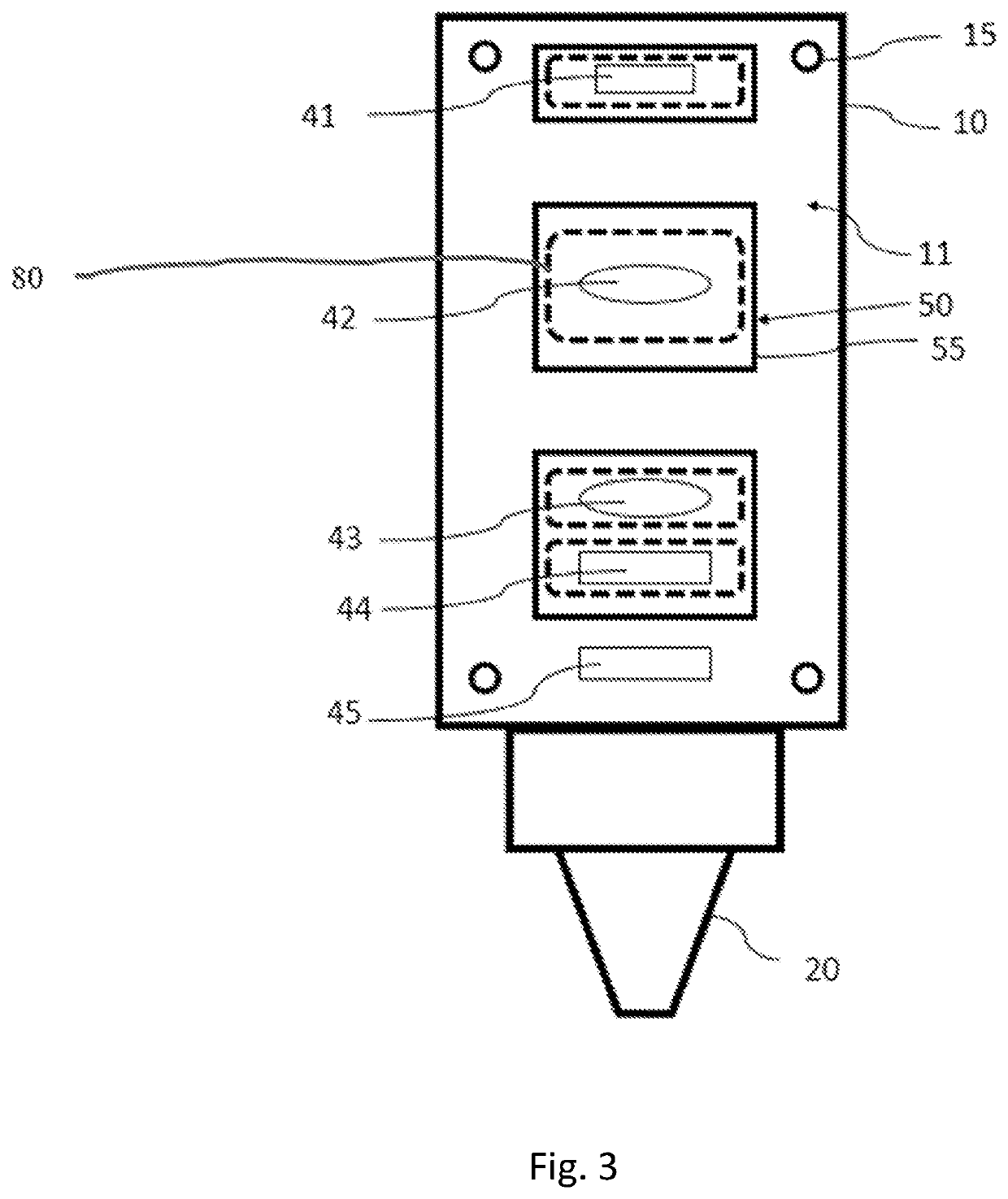
[0045]According to the present disclosure, the inventors have noted that the mounting surface 11 is the surface of the housing 10 that is best protected against dirt. Thus, the mounting surface 11 is selected for providing access openings to the optical components of the laser processing head. By moving the access openings from other surfaces of the housing to the mounting surface 11, the tightness of the housing 10 against dirt particles can be improved. Moreover, the other surfaces of the housing 10 besides the mounting surface 11 can be designed as integral surfaces, i.e. without gaps, interfaces or openings, thereby im...


PUM

PropertyMeasurementUnit
Wavelengthaaaaaaaaaa

Abstract

A laser processing head includes a housing including a mounting surface for mounting the laser processing head on a carrier; a plurality of optical components arranged within the housing; and an access opening formed in the housing for removing or inserting at least one first optical component among the optical components, the access opening being formed in the mounting surface.

Description

FIELD OF THE INVENTION[0001]The present disclosure relates to a laser processing head, in particular to a laser welding head or a laser cutting head, having a mounting surface for mounting the laser processing head to a carrier, and to a laser processing system including the same.BACKGROUND OF THE INVENTION[0002]Generally, a laser processing head for processing a workpiece using a laser beam is mounted at one surface of its housing, a so-called mounting surface, to a carrier of a laser processing system, which supports or moves the laser processing head during laser processing. Within the housing, the laser processing head includes an optical path for the laser beam in which a plurality of optical components are arranged, e.g. for focusing or collimating the laser beam. During processing of a workpiece, splashes of molten material and smoke are generated. The housing protects the optical components and other parts of the laser processing head against dirt particles, such as splashes...

Claims


Application Information

Patent Timeline
IPC IPC(8): B23K26/064B23K26/12B23K26/70
CPCB23K26/064B23K26/127B23K26/702
Inventor RUDOLF, ANDREAS
Owner PRECITEC GMBH
Why Eureka
Try Eureka