
System and method for controlling the impact of process and temperature in passive signal detector for automotive ethernet

a technology of automotive ethernet and passive signal detector, which is applied in the direction of logic circuits, transmissions, electric variable regulation, etc., can solve the problems of increased cost and weight of dedicated power on/off control cables, inaccurate thresholds for passive signal detection, and inability to accurately detect signals

Active Publication Date: 2021-07-06
AVAGO TECH INT SALES PTE LTD
View PDF2 Cites 0 Cited by
  • Summary
  • Abstract
  • Description
  • Claims
  • Application Information

AI Technical Summary

Benefits of technology

The patent text describes a system for detecting passive signals while compensating for process and temperature variations. The system includes a voltage level detector and two transistors. The first transistor has a threshold voltage of a first value, while the second transistor has a threshold voltage of the first value. An offset voltage is applied across the gate of the first transistor and the source of the second transistor, and a difference between the threshold voltage of the first value and the offset voltage is constant. This system allows for accurate detection of passive signals while compensating for process and temperature variations.

Problems solved by technology

A threshold for passive signal detection may be inaccurate due to process and temperature variations.
The large variation of Vth may cause inaccurate signal detection because Vth varies with temperature and process.
However, such dedicated power on / off control cables add extra cost and weight.

Method used


Image

  • System and method for controlling the impact of process and temperature in passive signal detector for automotive ethernet
  • System and method for controlling the impact of process and temperature in passive signal detector for automotive ethernet
  • System and method for controlling the impact of process and temperature in passive signal detector for automotive ethernet

Examples


Embodiment Construction

[0017]For purposes of reading the description of the various embodiments below, the following descriptions of the sections of the specification and their respective contents can be helpful:[0018]Section A describes a network environment and computing environment which can be useful for practicing embodiments described herein; and[0019]Section B describes embodiments of systems and methods for controlling the impact of process and temperature in passive signal detectors.

A. Computing and Network Environment

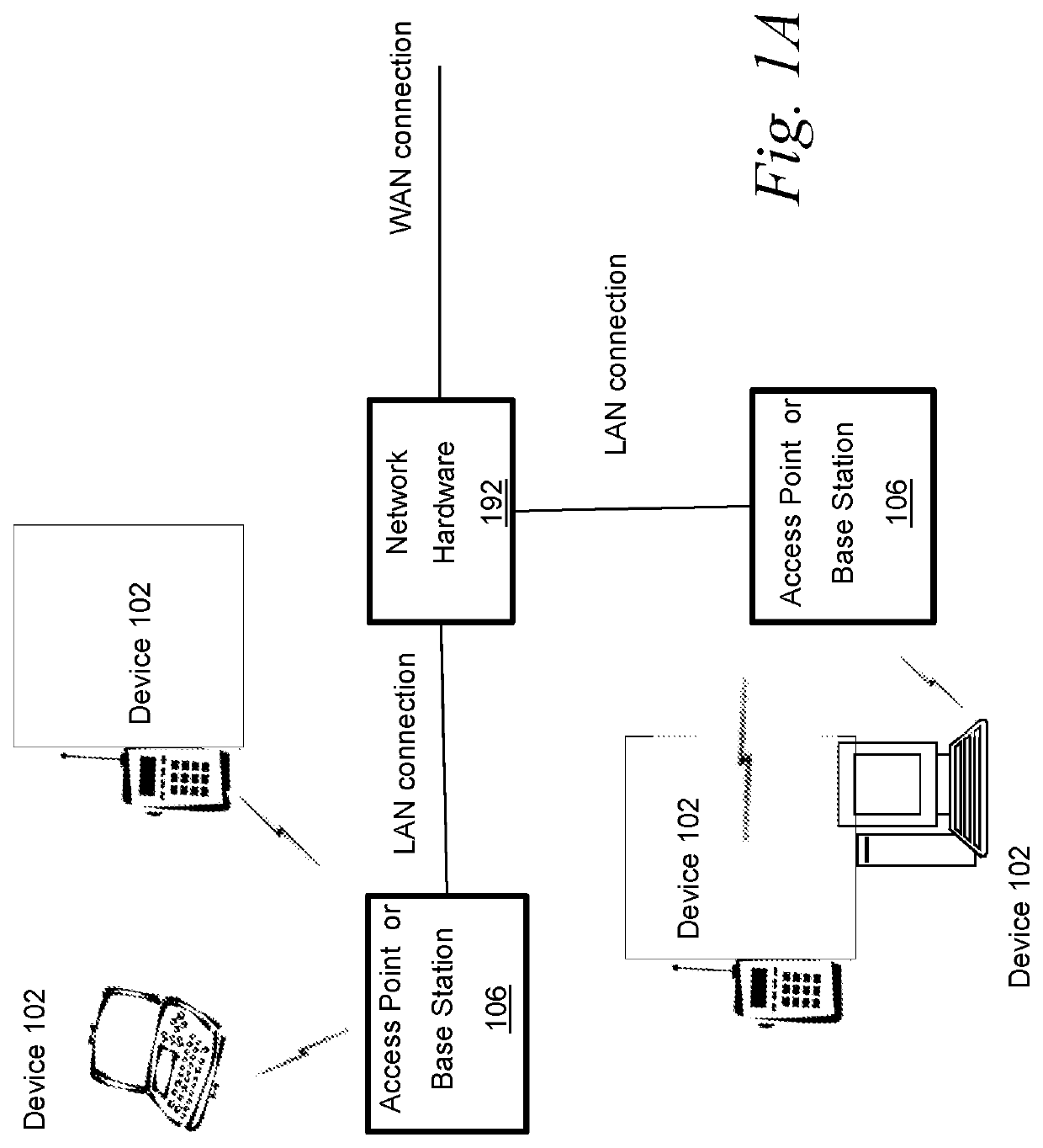
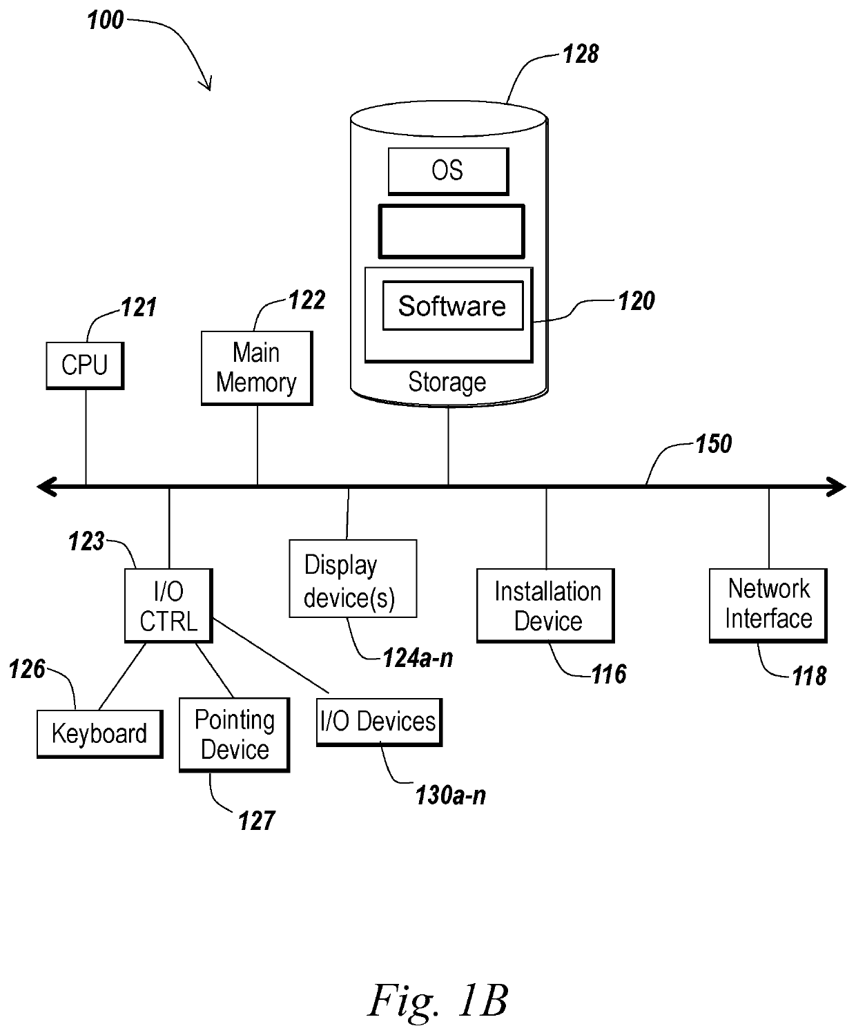
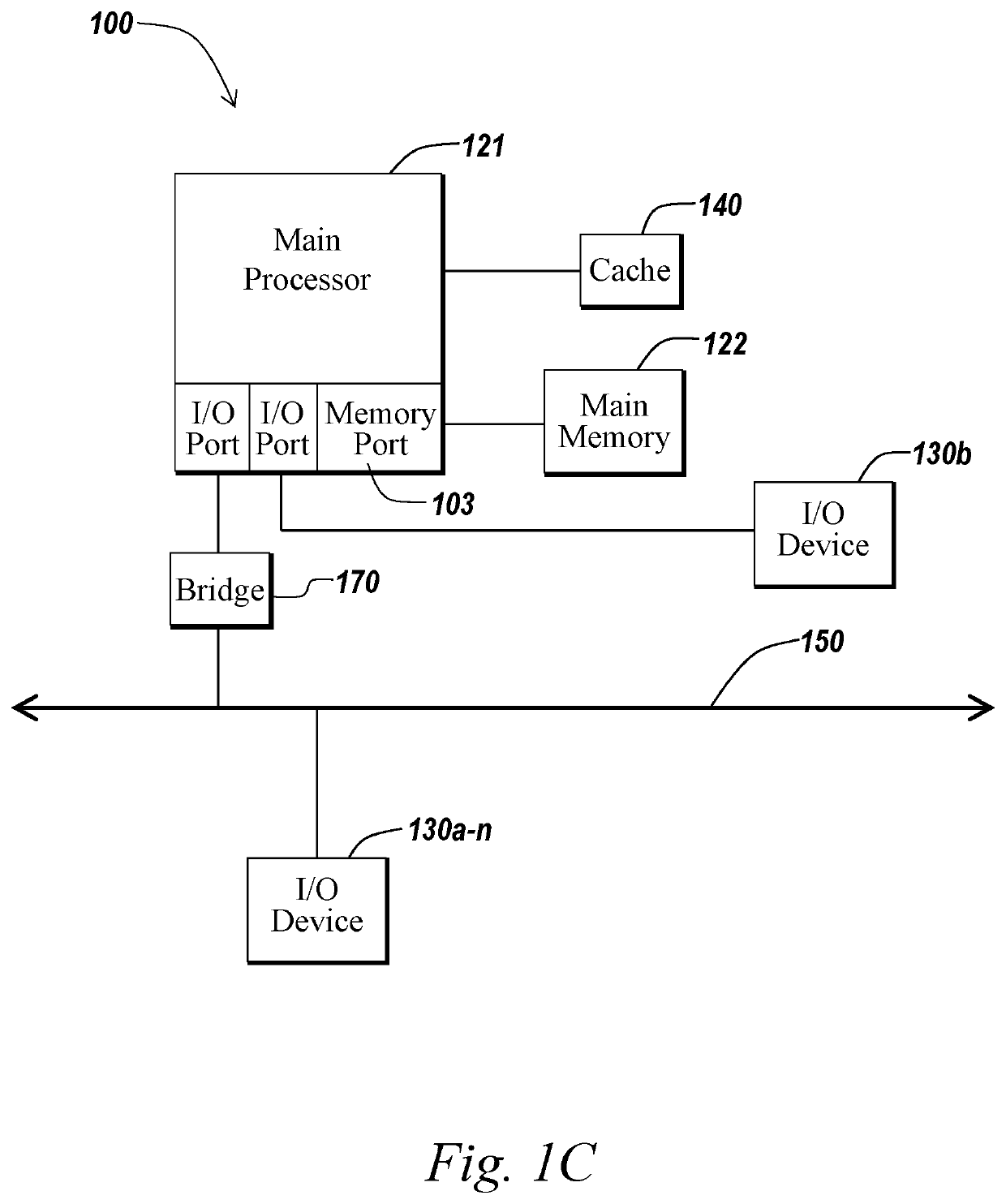
[0020]Prior to discussing specific embodiments of the present solution, aspects of a possible operating environment as well as associated system components (e.g., hardware elements) are described in connection with the methods and systems described herein. Referring to FIG. 1A, an embodiment of a network environment is depicted. In brief overview, the network environment includes a wireless communication system that includes one or more base stations 106, one or more wireless commun...


PUM


Abstract

A system for controlling the impact of process and temperature in passive signal detector includes a voltage level detector, a first transistor with a drain electrically connected to a first input of the voltage level detector, and a second transistor with a drain electrically connected to a second input of the voltage level detector. The first transistor has a threshold voltage of a first voltage value. The threshold voltage corresponds to a minimum gate-to-source voltage to create a conducting path between source and drain terminals of a transistor. The second transistor has a threshold voltage of the first voltage value. An offset voltage is applied across a gate of the first transistor and a source of the second transistor, and applied across a gate of the second transistor and a source of the first transistor. A difference between a threshold voltage and the offset voltage is constant.

Description

CROSS-REFERENCE TO RELATED APPLICATION[0001]This application claims the benefit of and priority to U.S. Provisional Application No. 62 / 718,221, entitled “System and Method for Controlling the Impact of Process and Temperature in Passive Signal Detector for Automotive Ethernet,” filed Aug. 13, 2018. U.S. Provisional Application No. 62 / 718,221 is hereby incorporated by reference herein in its entirety.FIELD OF THE DISCLOSURE[0002]This disclosure generally relates to systems and methods for controlling the impact of process and temperature in passive signal detector for automotive Ethernet, including but not limited to systems and methods for controlling the impact of the impact of process and temperature in passive signal detector.BACKGROUND OF THE DISCLOSURE[0003]A threshold for passive signal detection may be inaccurate due to process and temperature variations. To reduce power consumption in automotive electronics, it is desired to place inactive devices in sleep mode. Automotive E...

Claims


Application Information

Patent Timeline
Patent Type & Authority Patents(United States)
IPC IPC(8): G01R19/165H04L12/40
CPCG01R19/16504G01R19/16576H04L12/40H04L2012/40273G05F1/567H03K19/00384G06F1/3206
Inventor VAKILIAN, KAMBIZWANG, JINGGUANGDHAMDHERE, VIKRANT
Owner AVAGO TECH INT SALES PTE LTD
Learn More