
Surgical bone staple device and method of use

a bone stabilization device and bone stabilization technology, applied in the field of surgical bone stabilization devices, can solve the problems of traumatic to the tendons, time-consuming process of tying down sutures individually and tying down, and complex process, so as to reduce excess bone and tissue loss and trauma, quick and efficient secure the rotator, and increase the effect of pulling strength

Active Publication Date: 2021-06-29
ANAKWENZE OKE ADRIAN
View PDF26 Cites 5 Cited by
  • Summary
  • Abstract
  • Description
  • Claims
  • Application Information

AI Technical Summary

Benefits of technology

The device described in this patent is a tool that allows surgeons to quickly and easily secure the rotator cuff to the bone in a single step process. It uses a staple and a bracket to hold the tendon in place. The staple is small enough to minimize damage to the bone and surrounding tissues, but strong enough to provide enough strength and compression. The staple may be made of metal or absorbable material, and may be coated with collagen scaffolds to encourage healing. This technology can be used in a variety of surgeries that require suture anchors to secure tissue to bone, making the procedure faster and easier and potentially increasing the rate of healing.

Problems solved by technology

This process can be fairly complex depending on training, experience and tear pattern.
In addition, it can be a time-consuming process passing sutures individually and tying down.
The respective sutures used are heavily braided and are known to be traumatic to the tendons.
Multiple needle passages can be traumatic to already torn and degenerated tissue.
Proper tension / compression is not always achievable with sutures.
There is also the issue of “knot security”.
Knots can become undone or loose.

Method used


Image

  • Surgical bone staple device and method of use
  • Surgical bone staple device and method of use
  • Surgical bone staple device and method of use

Examples


embodiment 301

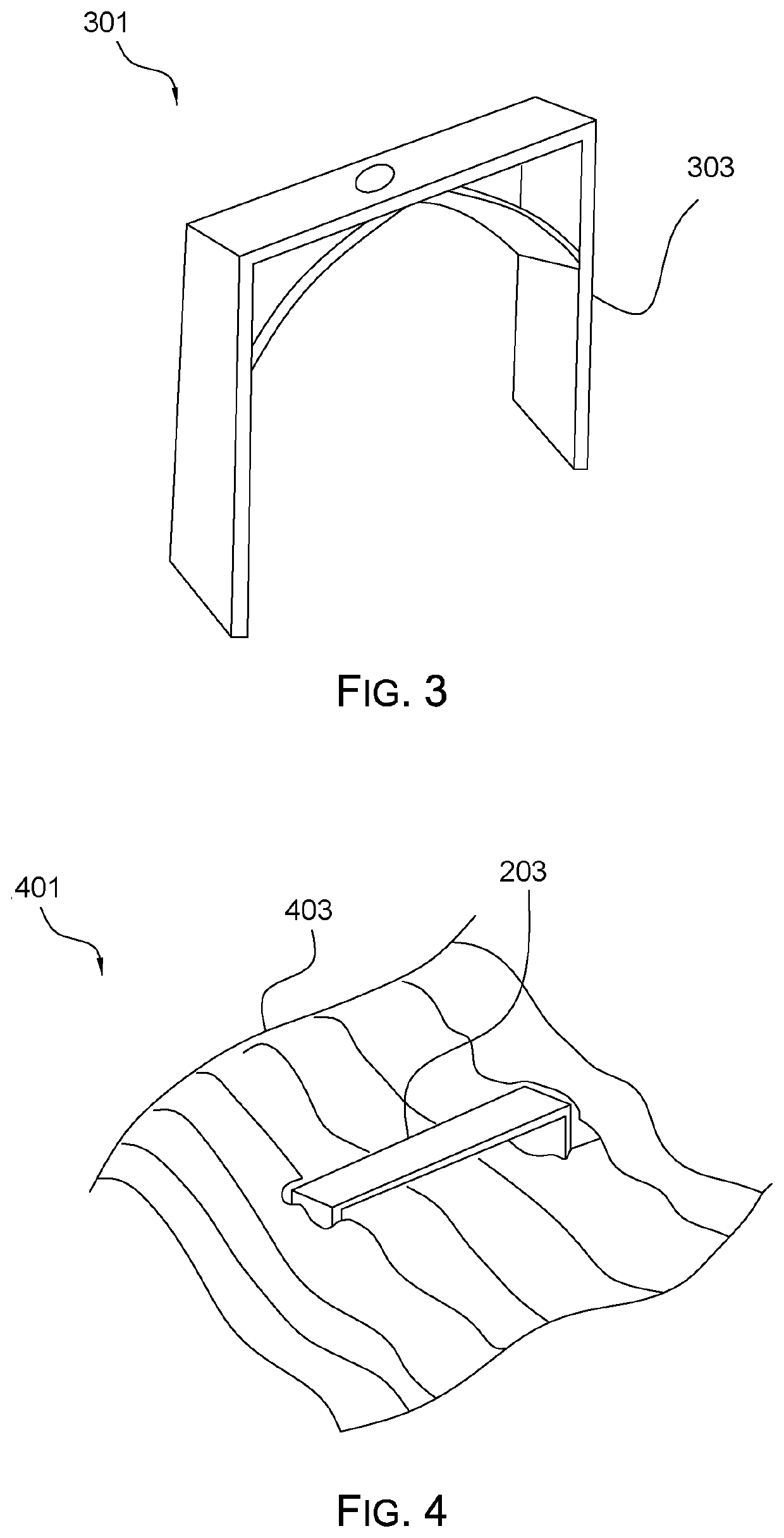
[0029]An alternative embodiment 301 of staple 203 is shown in FIG. 3 which indicates the staple having a depth stop 303 to limit the depth at which the staple may be set within the bone.

embodiment 401

[0030]An alternative embodiment 401 of staple 203 is shown in FIG. 4 which would indicate a biologic material 403 or other bio-compatible material that does not impair tissue growth to provide additional cushion and a better healing environment to the staple 203.

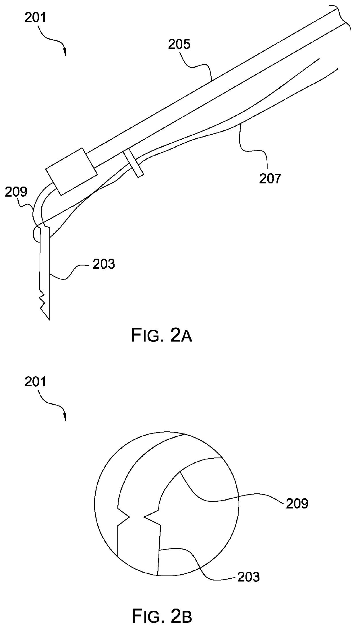
[0031]FIG. 5 shows a second staple implant mechanism 501 defining a staple receiver 509, a staple push member 503 having a staple contact surface engaging the upper bridge of a two pronged staple, the rear surface connecting a threaded rod 507 which exits a rear portion of the staple receive and is connected to an expanded screw knob 505, wherein the staple is forcibly deployed from the staple receiver into the target tissue 511 by rotation of the expanded screw knob 505 advancing the staple 203 outward from the staple receiver 509.

[0032]FIG. 6 shows a two pronged staple 601 with an expanded width bridge 603 to lessen the force of the bridge 603 against underlying soft tissue and to spread the force of the bridge over a grea...


PUM


Abstract

A surgical bone staple device enables low impact installation of fasteners in bones, soft tissue and the like via a delivery tool. The staples have various support structure in the bridge area to lower pressure or healing potential. The staples could also have barbs or other features to facilitate holding the staple in place.

Description

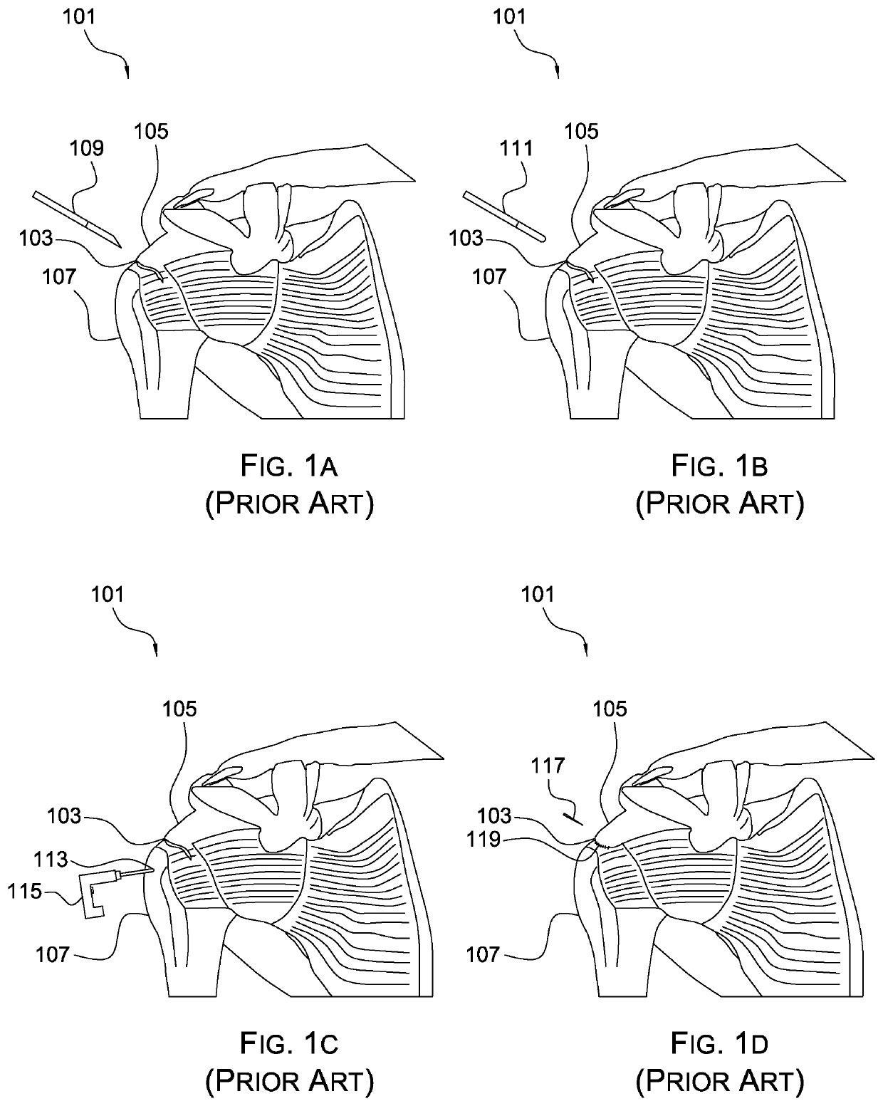
BACKGROUND1. Field of the Invention[0001]The present invention relates generally to surgical bone stable devices and methods of use.2. Description of Related Art[0002]Bone staple devices for orthopedic surgical procedures are well known in the art. In FIGS. 1A, 1B, 1C and 1D, a common rotator cuff repair 101 is depicted. A tear 103 in tissue between the arm 107 and the shoulder 105 is cleaned by a scalpel 109. The edges of the clean tear 103 are prepared by roughing them with a tool 111. Holes are created by drill 115 and bit 113 to enable suture 117 to join the tendon 119 and the bone 107.[0003]Conventional staple devices include having a staple frame attached to an insertion handle with a frangible joint, the handle use for placement of the staple, subsequently removed after installation by the fracture of the frangible joint. During use, the staple may be presented in an offset or angular position relative to the axis of the handle, and may be pushed into the bone or used with a ...

Claims


Application Information

Patent Timeline
Patent Type & Authority Patents(United States)
IPC IPC(8): A61B17/068A61F2/08A61B17/04A61B17/064A61B17/00A61B17/072
CPCA61B17/0682A61B17/0401A61B17/0483A61B17/0642A61F2/0811A61B17/068A61B17/072A61B17/07207A61B2017/00893A61B2017/0409A61B2017/0464A61B2017/0646A61F2002/0835A61F2002/0852A61B17/07292A61B2017/0414A61B2017/0427A61B2017/0641A61F2/08A61B2090/036A61B2090/037
Inventor ANAKWENZE, OKE ADRIAN
Owner ANAKWENZE OKE ADRIAN
Learn More