
Rigging device

a technology of rigging device and rigging rod, which is applied in the direction of load-engaging elements, curtain suspension devices, stands/trestles, etc., can solve the problems of inability to safely, quickly and efficiently repeatedly lift large amounts of long, heavy stock, and inherently dangerous lifting of heavy equipment with cranes. , to achieve the effect of convenient use, low cost, and quick and efficient secure and release of loads

Inactive Publication Date: 2009-01-22
SWISHER JOHN R
View PDF11 Cites 1 Cited by
  • Summary
  • Abstract
  • Description
  • Claims
  • Application Information

AI Technical Summary

Benefits of technology

[0004]It is an object of the invention to provide a rigging device used to secure long, heavy loads or stock, such as long, heavy metal or steel beams, joist, girders, trusses, and the like, to a hoist line of a crane which is low in cost, which is safe, which is constructed and arranged to quickly and efficiently secure and release loads, and which is easy to use and highly reliable.

Problems solved by technology

The lifting of heavy equipment with cranes is inherently dangerous.
Lifting a long, heavy beam with a crane is difficult because it is unwieldy, and must be attached to the hoist line of a crane carefully to ensure the weight of the beam is balanced relative to the lifting axis of the hoist line to prevent the beam from shifting or displacing during lifting.
The challenge of providing a reliable and quick coupling and decoupling between the hoist line of a crane and long, heavy stock further contributes to the difficultly of safely, rapidly, and efficiently repeatedly lifting large amounts of long, heavy stock.

Method used


Image

  • Rigging device
  • Rigging device
  • Rigging device

Examples


Embodiment Construction

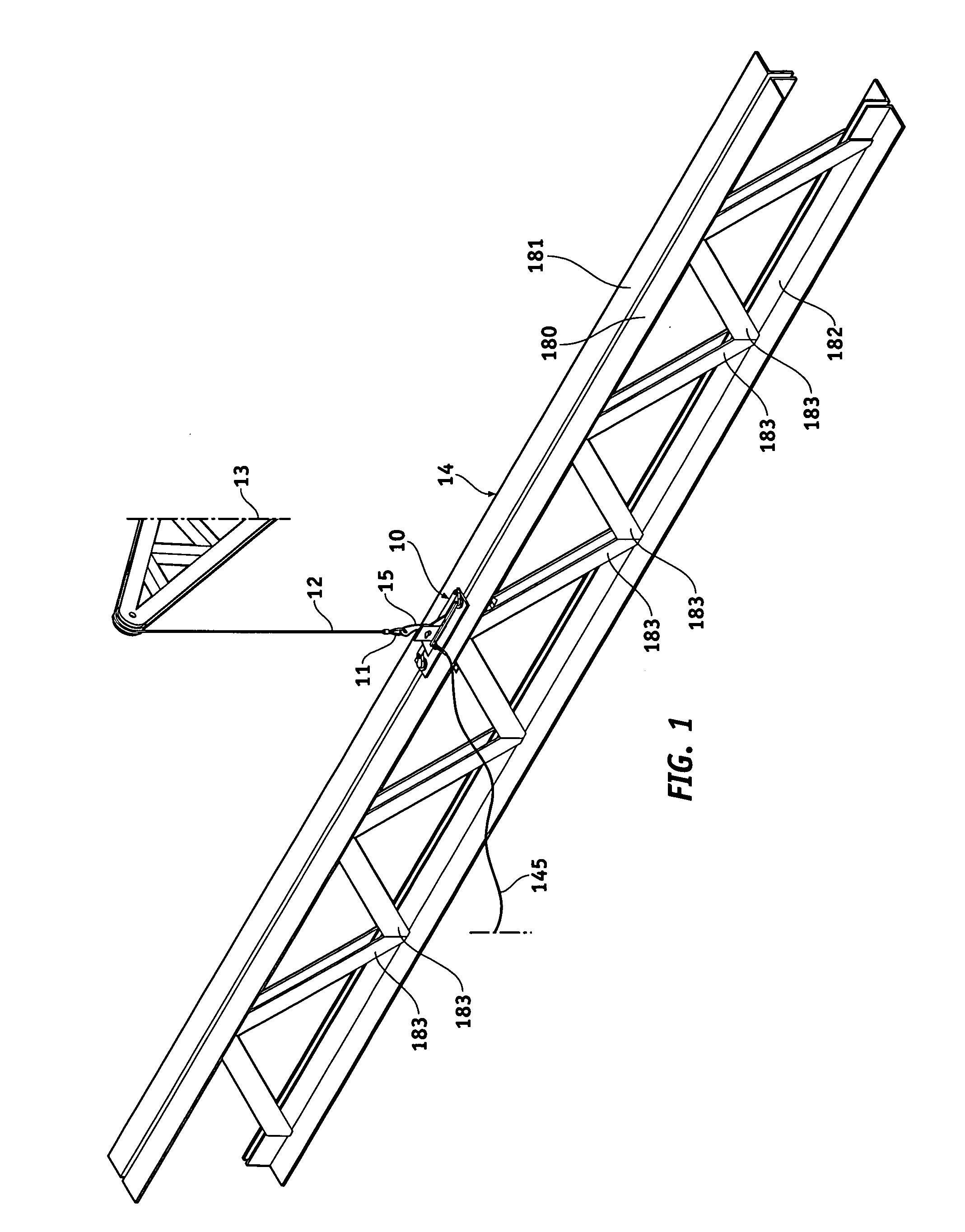
[0016]Turning now to the drawings, in which like reference characters indicate corresponding elements throughout the several views, attention is first directed to FIG. 1, in which there is seen a rigging device 10 coupled between a business end 11 of a hoist line 12 managed by a crane 13 that is only partially shown, and a truss or beam 14 securing business end 11 of hoist line 12 to beam 14 in a lifting operation. In the present embodiment, business end 11 of hoist line 12 is formed with a hook 15 that hookingly secures rigging device 10, further details of which will be discussed later in this specification.

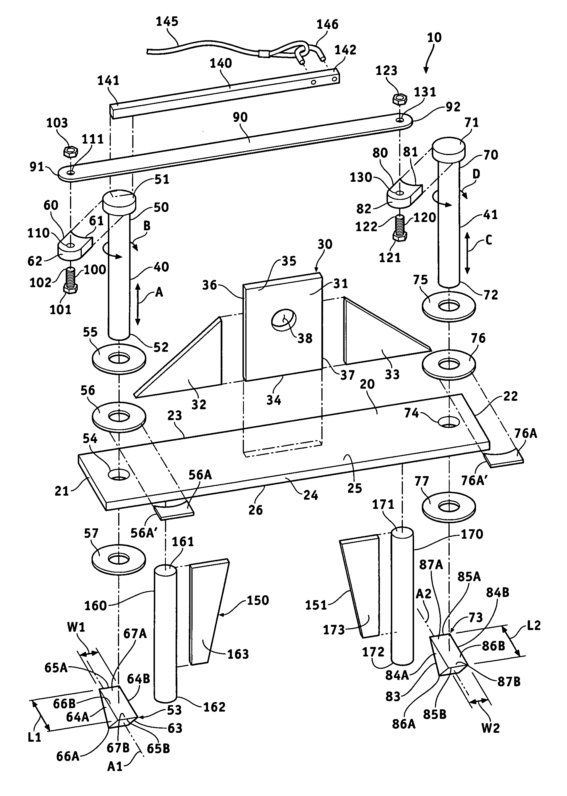
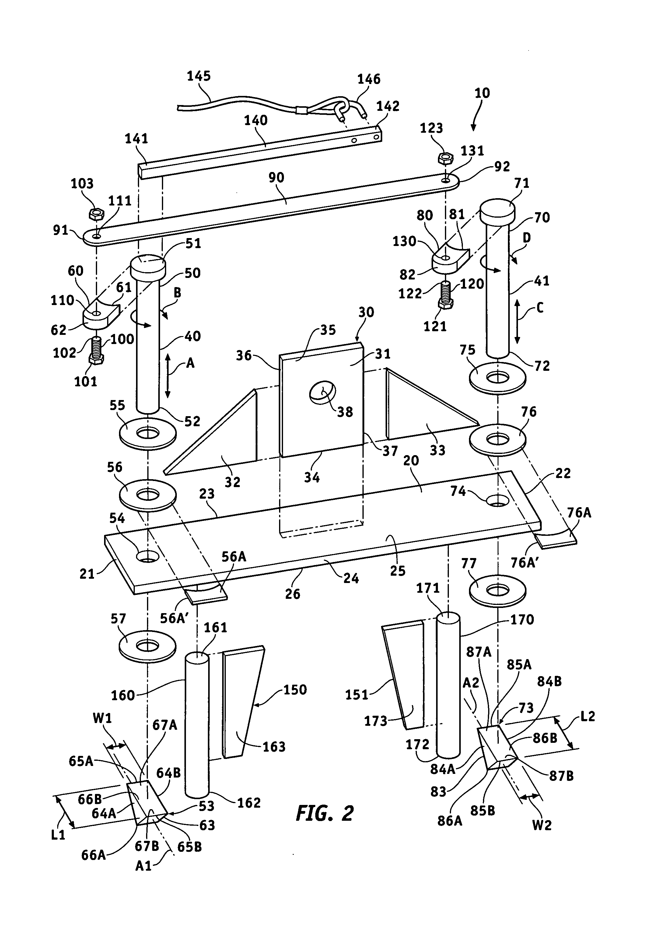
[0017]Referencing FIG. 2, rigging device 10 is constructed of steel, aluminum, or other strong, rugged, resilient metal, metal alloy, or the like, and consists of an elongate fixture 20 having opposed ends 21 and 22, opposed sides 23 and 24, and opposed upper and lower surfaces or faces 25 and 26. Fixture 20 is base of rigging device 10 to which the various components thereof a...


PUM


Abstract

A rigging device includes a fixture having opposed first and second ends, opposed upper and lower faces, and a bracket extending away from the upper face of the fixture between the opposed first and second ends of the fixture to engage a hoist line of a crane. A support is mounted to the fixture proximate each of the opposed first and second ends on either side of the bracket extending away from the lower face of the fixture terminating with an engaging element movable between a disengaging position and an engaging position.

Description

CROSS-REFERENCE TO RELATED APPLICATION[0001]This application claims the benefit of U.S. Provisional Patent Application Ser. No. 60 / 959,678, filed Jul. 16, 2007.FIELD OF THE INVENTION [0002]The present invention relates to rigging devices used to secure loads in lifting operations.BACKGROUND OF THE INVENTION [0003]The lifting of heavy equipment with cranes is inherently dangerous. Of particular significance is the lifting of long, heavy beams, such as long, heavy, metal or steel beams, with cranes. Lifting a long, heavy beam with a crane is difficult because it is unwieldy, and must be attached to the hoist line of a crane carefully to ensure the weight of the beam is balanced relative to the lifting axis of the hoist line to prevent the beam from shifting or displacing during lifting. This is particularly important in steel girder operations where precise placement for installation is required, such as in the building of the steel infrastructure of buildings, bridges, and the like. ...

Claims


Application Information

Patent Timeline
Patent Type & Authority Applications(United States)
IPC IPC(8): F16M13/00
CPCB66C1/28
Inventor SWISHER, JOHN R.
Owner SWISHER JOHN R
Learn More