
Fuel cell system and control method of fuel cell system

a fuel cell and control method technology, applied in the direction of fuel cells, motive system fuel cells, electrical devices, etc., can solve the problems of oil in the housing leaking to the supply passage and flowing into the fuel cell

Active Publication Date: 2021-05-25
TOYOTA JIDOSHA KK
View PDF5 Cites 0 Cited by
  • Summary
  • Abstract
  • Description
  • Claims
  • Application Information

AI Technical Summary

Benefits of technology

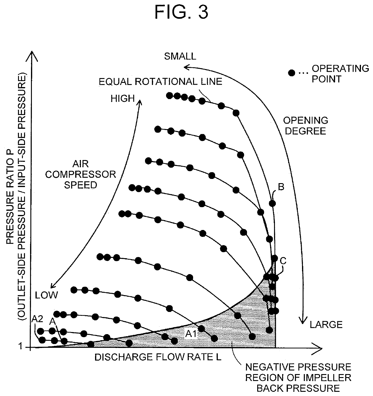
[0004]In the above-described related art, more oxidant gas is discharged from the supply passage when the bypass pressure-regulating valve is opened more. Hence, the pressure inside the housing may become higher than an impeller back face pressure. When the pressure inside the housing becomes higher than the impeller back face pressure, the oil in the housing may leak to the supply passage and flow into the fuel cell. Accordingly, there is a demand for a technology that can reduce the possibility of the oil in the housing leaking to the supply passage.
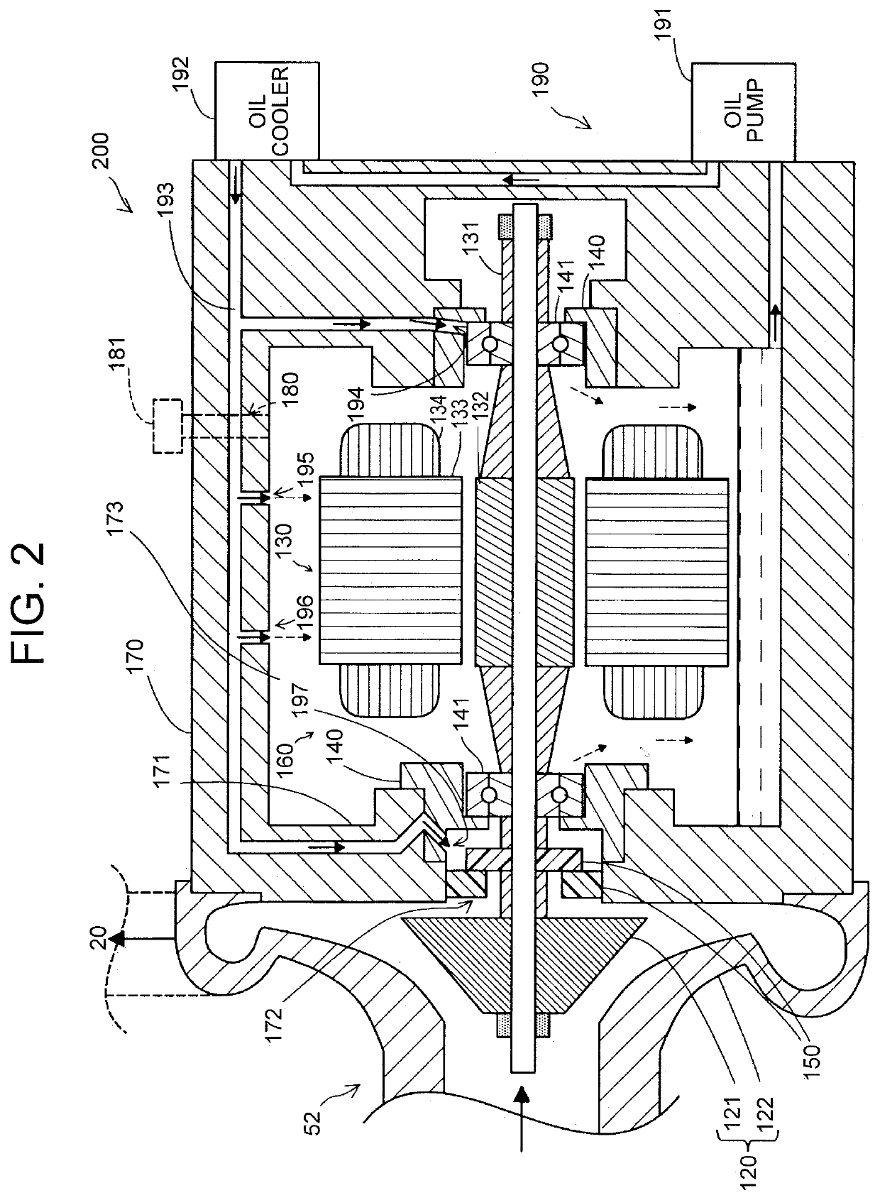
[0005](1) A first aspect of the present disclosure relates to a fuel cell system including: a fuel cell stack; a fuel gas supply mechanism that supplies fuel gas to the fuel cell stack; an oxidant gas supply and discharge mechanism including an air compressor that supplies oxidant gas to the fuel cell stack; and a controller that controls supply of the fuel gas and the oxidant gas to control generation of electric power by the fuel cell stack. The oxidant gas supply and discharge mechanism has: an oxidant gas supply and discharge passage that passes the oxidant gas; and a pressure-regulating valve disposed on a downstream side of the air compressor in the oxidant gas supply and discharge passage. The air compressor has: an impeller disposed in the oxidant gas supply and discharge passage to deliver the oxidant gas; a motor configured to rotate the impeller; a housing that houses the motor and divides an area where the motor is disposed from the oxidant gas supply and discharge passage where the impeller is disposed; and a shaft that extends through the housing to couple a rotary shaft of the motor with a rotary shaft of the impeller. The controller executes at least one of a first process and a second process, the first process being executed for increasing a speed of the impeller after decreasing an opening degree of the pressure-regulating valve in a first operation where both decreasing the opening degree of the pressure-regulating valve and increasing the speed of the impeller are performed, the second process being executed for increasing the opening degree of the pressure-regulating valve after decreasing the speed in a second operation where both increasing the opening degree of the pressure-regulating valve and decreasing the speed are performed. According to the fuel cell system, the controller executes at least one of the first process for increasing the speed after decreasing the opening degree of the pressure-regulating valve in the first operation, and the second process for increasing the opening degree of the pressure-regulating valve after decreasing the speed in the second operation. Accordingly, at least in one of the cases where the first operation is performed and where the second operation is performed, it is possible to suppress the situation where the impeller back face pressure, that is the pressure inside a space between the impeller and the housing in the oxidant gas supply and discharge passage, becomes negative. Hence, a leakage of the oil in the housing to the outside (the oxidant gas supply and discharge passage) can be suppressed.
[0006](2) In the fuel cell system of the above aspect, the controller may execute the first process without determining whether or not an impeller back face pressure, that is a pressure inside a space between the impeller and the housing in the oxidant gas supply and discharge passage, becomes negative in the first operation, and execute the second process without determining whether or not the impeller back pressure becomes negative in the second operation. The fuel cell system makes it possible to determine whether or not to execute the first process and the second process without determining whether or not the impeller back pressure becomes negative. Hence, the fuel cell system can reduce the possibility of complicated control performed by the controller.
[0007](3) In the fuel cell system of the above aspect, the controller may determine whether or not an impeller back pressure, that is a pressure inside a space between the impeller and the housing in the oxidant gas supply and discharge passage, becomes negative, with use of data obtained in advance, the data indicating an operating point that represents a combination of the opening degree of the pressure-regulating valve and the speed of the impeller that makes the impeller back pressure negative, execute the first process, when the impeller back pressure becomes negative at least in a case where increasing the speed is executed first in the first operation, and execute the second process, when the impeller back pressure becomes negative at least in a case where increasing the opening degree is executed first in the second operation. The fuel cell system can enhance the degree of freedom of control on the pressure-regulating valve and the air compressor when there is no possibility of occurrence of negative pressure.
[0008](4) A second aspect of the present disclosure relates to a control method of a fuel cell system. The fuel cell system includes a fuel cell stack, a fuel gas supply mechanism that supplies fuel gas to the fuel cell stack, an oxidant gas supply and discharge mechanism including an air compressor that supplies oxidant gas to the fuel cell stack, and a controller that controls supply of the fuel gas and the oxidant gas to control electric power generation by the fuel cell stack. The oxidant gas supply and discharge mechanism has an oxidant gas supply and discharge passage that passes the oxidant gas, and a pressure-regulating valve disposed on a downstream side of the air compressor in the oxidant gas supply and discharge passage. The air compressor has an impeller disposed in the oxidant gas supply and discharge passage to deliver the oxidant gas, a motor configured to rotate the impeller, a housing that houses the motor and divides an area where the motor is disposed from the oxidant gas supply and discharge passage where the impeller is disposed, and a shaft that extends through the housing to couple a rotary shaft of the motor with a rotary shaft of the impeller. The control method comprises executing at least one of a first process and a second process by controller, the first process being executed for increasing a speed of the impeller after decreasing an opening degree of the pressure-regulating valve in a first operation where both decreasing the opening degree of the pressure-regulating valve and increasing the speed of the impeller are performed, the second process being executed for increasing the opening degree of the pressure-regulating valve after decreasing the speed in a second operation where both increasing the opening degree of the pressure-regulating valve and decreasing the speed are performed. According to the control method of a fuel cell system of this aspect, the controller executes at least one of the first process for increasing the speed after decreasing the opening degree of the pressure-regulating valve in the first operation and the second process for increasing the opening degree of the pressure-regulating valve after decreasing the speed in the second operation. Accordingly, at least in one of the cases where the first operation is performed and where the second operation is performed, it is possible to suppress the situation where the impeller back pressure becomes negative. Hence, a leakage of the oil in the housing to the outside (oxidant gas supply and discharge passage) can be suppressed.

Problems solved by technology

When the pressure inside the housing becomes higher than the impeller back face pressure, the oil in the housing may leak to the supply passage and flow into the fuel cell.

Method used


Image

  • Fuel cell system and control method of fuel cell system
  • Fuel cell system and control method of fuel cell system
  • Fuel cell system and control method of fuel cell system

Examples


first embodiment

A. First Embodiment

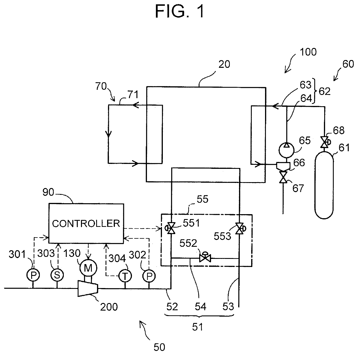
[0018]FIG. 1 is a schematic view of a fuel cell system 100 according to a first embodiment. In the present embodiment, the fuel cell system 100 generates electric power by a reaction of fuel gas (anode gas) and oxidant gas (cathode gas). For example, the fuel cell system 100 is mounted on a fuel cell vehicle, and is used as a power generator for driving a driving motor. The fuel cell system 100 includes a fuel cell stack 20, an oxidant gas supply and discharge mechanism 50, a fuel gas supply mechanism 60, a coolant circulation mechanism 70, and a controller 90. The coolant circulation mechanism 70, which is connected to the fuel cell stack 20, has a coolant circulation passage 71 that passes coolant (for example, water), and a pump (not shown) that pumps the coolant.

[0019]The fuel cell stack 20 has a stack structure formed by stacking a plurality of fuel cell unit cells (not shown). In the present embodiment, each of the fuel cell unit cells that constitute the fu...

second embodiment

B. Second Embodiment

[0050]FIG. 6 is a flowchart of an operating point changing process executed by the controller 90 of the fuel cell system 100 according to a second embodiment. FIG. 7 is a second drawing showing the relationship between the operating point and the negative pressure region. In FIG. 6, when the process similar to the process shown in FIG. 5 is executed, the process is designated by the similar reference sign.

[0051]The fuel cell system 100 according to the second embodiment is different from the fuel cell system 100 according to the first embodiment in the contents of the operating point changing process executed by the controller 90. In the first embodiment, when the first operation is executed, the first process (steps S111 to S113 of FIG. 5) is executed regardless of whether or not the impeller back face pressure may become negative. When the second operation is executed, the second process (steps S121 to S123 of FIG. 5) is executed regardless of whether or not th...

third embodiment

C-1. Third Embodiment

[0055]In the above embodiments, although the controller 90 executes both the first process and the second process, the present disclosure is not limited to this configuration. The controller 90 may execute only one of the first process and the second process. For example, the controller 90 may execute the first process when performing the first operation, and execute normal control when performing the second operation. This makes it possible to suppress the impeller back face pressure becoming negative when the first operation is performed. For example, the controller 90 may execute the second process, when performing the second operation, and execute normal control when performing the first operation. This makes it possible to suppress the impeller back face pressure becoming negative when the second operation is performed. In both the configurations, it is possible to suppress the impeller back pressure becoming negative in one of the cases where the first ope...


PUM

PropertyMeasurementUnit
areaaaaaaaaaaa
speedaaaaaaaaaa
pressureaaaaaaaaaa

Abstract

A fuel cell system includes: an air compressor that sends out oxidant gas to a fuel cell stack, including a motor, a housing, and an impeller; an oxidant gas supply and discharge passage; a pressure-regulating valve; and a controller. The controller executes at least one of a first process and a second process, the first process being executed for increasing a speed of the impeller after decreasing an opening degree of the pressure-regulating valve in a first operation where both decreasing the opening degree of the pressure-regulating valve and increasing the speed of the impeller are performed, the second process being executed for increasing the opening degree of the pressure-regulating valve after decreasing the speed in a second operation where both increasing the opening degree of the pressure-regulating valve and decreasing the speed are performed.

Description

INCORPORATION BY REFERENCE[0001]The disclosure of Japanese Patent Application No. 2017-235251 filed on Dec. 7, 2017 including the specification, drawings and abstract is incorporated herein by reference in its entirety.BACKGROUND1. Technical Field[0002]The present disclosure relates to a fuel cell system and a control method of the fuel cell system.2. Description of Related Art[0003]There is known a fuel cell system that includes a fuel cell, an air compressor that supplies oxidant gas to the fuel cell, and a supply passage that passes the oxidant gas supplied to the fuel cell (for example, Japanese Patent Application Publication No. 2017-126540). The air compressor includes an impeller disposed in the supply passage of the oxidant gas, a motor configured to rotate the impeller, a housing that divides an area where the motor is disposed from the supply passage, and a shaft that extends through the housing to couple a rotary shaft of the motor with a rotary shaft of the impeller. In ...

Claims


Application Information

Patent Timeline
Patent Type & Authority Patents(United States)
IPC IPC(8): H01M8/04111H01M8/04007H01M8/0662H01M8/04746H01M8/04089
CPCH01M8/04111H01M8/04007H01M8/04089H01M8/04753H01M8/0662H01M2250/20
Inventor SHIMASAKI, SHINOBU
Owner TOYOTA JIDOSHA KK
Learn More