Dial applique for a timepiece

a timepiece and dial technology, applied in the field of mechanical horology, can solve the problems of not being able to weld gold appliques onto ceramic dials, limiting the materials that can be used to make appliques and dials, and unable to use fragile dials. , to achieve the effect of simple assembly, excellent hold, and robust and stable method

Active Publication Date: 2021-05-04
THE SWATCH GRP RES & DEVELONMENT LTD
View PDF22 Cites 1 Cited by
  • Summary
  • Abstract
  • Description
  • Claims
  • Application Information

AI Technical Summary

Benefits of technology

[0008]More precisely, it is an object of the invention to provide an applique or applied chapter permitting simple assembly on the dial while ensuring an excellent hold.
[0010]It is another object of the invention to provide an applique or applied chapter permitting reversible assembly on the dial, allowing the applique to be changed without damaging the dial.
[0011]It is another object of the invention to provide an applique that removes any constraints in the choice of materials for the dial and for the applique.
[0012]It is another object of the invention to provide a robust and stable method for affixing an applique to a dial.
[0020]The invention makes it possible to obtain secure, reversible fastening of an applique to a dial with no constraints as to the choice of materials and allowing an automated inspection to be made of the quality of the fastening of the applique to the dial by visual means which are preferably non-destructive.

Problems solved by technology

Riveting requires the application of a certain amount of force on the foot portion in order to deform the material, so this technique cannot be used for fragile dials.
To affix appliques by welding requires the selection of suitable materials, which limits the possible materials that can be used to make the appliques and the dial.
For example, it is not possible to weld gold appliques onto a ceramic dial.
Moreover, if the assembly is unsatisfactory, it is not then possible, when the appliques are affixed by welding or adhesive bonding, to remove improperly positioned appliques or to make adjustments without damaging the dial.
Finally, known techniques for assembling appliques on a dial, such as riveting, welding or adhesive bonding, all have the drawback of not allowing inspection of the hold of the appliques on all the assembled pieces.
Indeed, once the applique is assembled to the dial, the quality of its fastening cannot be reliably tested in a non-destructive manner.
Quality control cannot therefore be applied to the entire product.
Further, it is not possible to make an automated visual inspection simply by taking a photograph of the exterior of the assembly.
Indeed, the deformations of the foot portion obtained by riveting are too different from each other, making automated interpretation of the results very complex.

Method used


Image

  • Dial applique for a timepiece
  • Dial applique for a timepiece

Examples


first embodiment

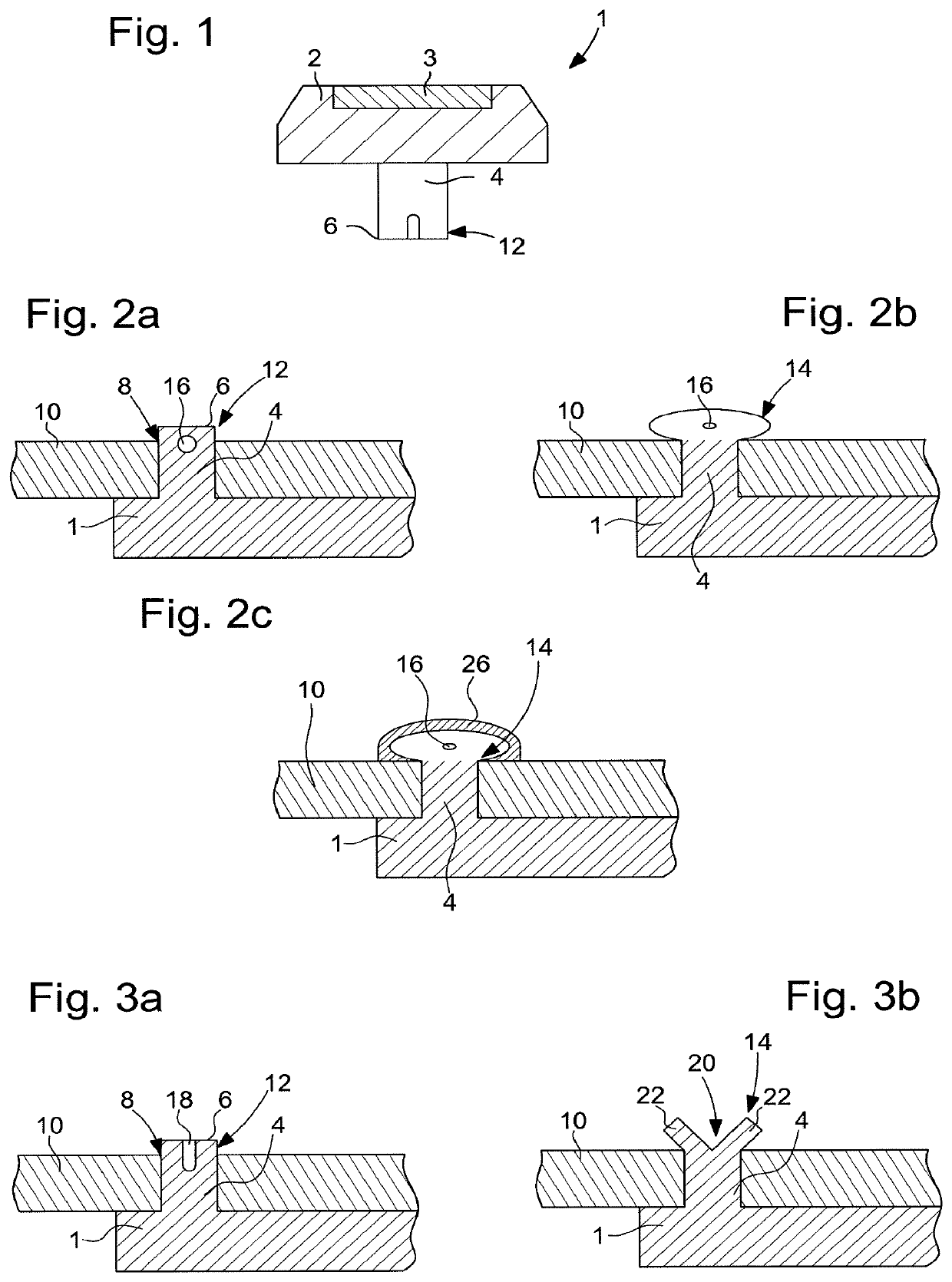
[0039]In the first embodiment represented in FIGS. 2a, 2b, 3a and 3b, dial 10 is planar so that the height of hole 8 is equal to the height of dial 10. The locking area 14 thus projects from the overall surface of dial 10.

second embodiment

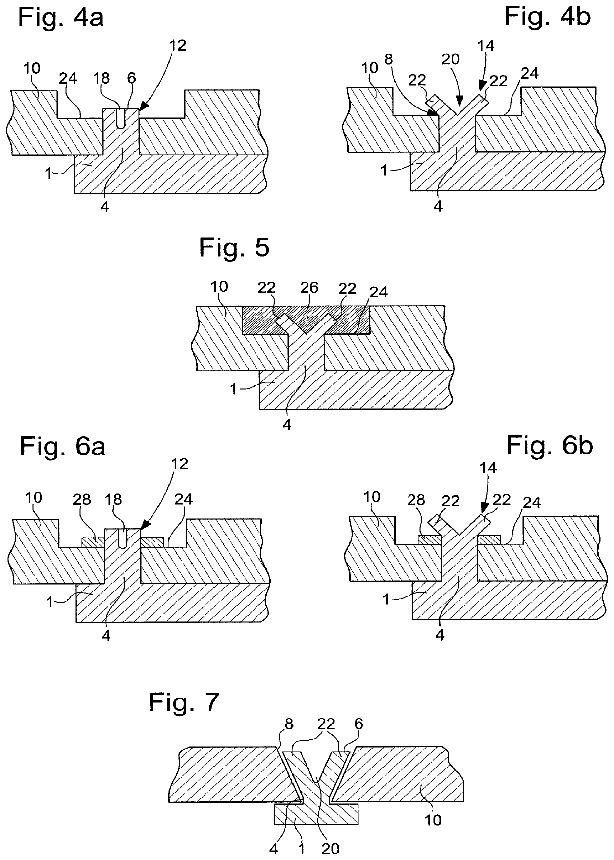
[0040]In a second embodiment represented in FIGS. 4a, 4b, 5 and 6a, 6b, dial 10 comprises a recess 24 inside which through hole 8 is formed, and the height of hole 8 is equal to the height of the dial under recess 24. Thus, locking area 14 is embedded in dial 10 and does not project from the overall surface of dial 10.

[0041]In a third embodiment represented in FIG. 5, derived from the second embodiment, recess 24 is filled with a permanent means 26 of fastening to the dial, such as adhesive, to cover the part of foot portion 4 projecting from hole 8. This variant reinforces the assembly. If the assembly is checked by visual means, the adhesive will evidently by deposited after said inspection, once the assembly has been validated. The addition of a permanent fastening means also allows the position of locking area 14 to be fixed by filling the space formed between lugs 22.

[0042]In a fourth embodiment represented in FIGS. 6a and 6b, derived from the second embodiment, a spacer 28 is ...

fifth embodiment

[0043] represented in FIG. 7, foot portion 4 has a height lower than or equal to the height of hole 8. Hole 8 has an area of conical cross-section whose dimensions are greater than the dimensions of the foot portion 4 prior to the deformation of plastically deformable area 12, to allow insertion of the foot portion into hole 8 prior to deformation. Further, the dimensions of the area of conical cross-section are chosen such that locking area 14 abuts against said area of conical cross-section. More specifically, as represented in FIG. 7, lugs 22 form an inverted cone which is inscribed within the area of conical cross-section of hole 8 such that said lugs 22 abut against the walls of hole 8 preventing any removal of foot portion 4 from hole 10. It is evident that this variant can be combined with the embodiment with the hole inside a recess, and with the use of permanent means of fastening to the dial to cover locking area 14 and fill at least hole 8.

[0044]The present invention also...


PUM


Abstract

An applique is intended to be affixed to a timepiece dial, and includes at least one foot portion having a first end attached to the applique and a second, free end, the foot portion being arranged to be capable of insertion into a hole provided in the dial. The foot portion includes, on the side of the free end thereof, a plastically deformable area arranged to form, after deformation, once the foot portion is inserted into the hole in the dial, at least one locking area of the foot portion on the dial.

Description

[0001]This application claims priority from European Patent application 15201680.4 of Dec. 21, 2015, the entire disclosure of which is hereby incorporated herein by reference.FIELD OF THE INVENTION[0002]The invention relates to the field of mechanical horology. It concerns, more particularly, an applique or applied chapter intended to be affixed to a timepiece dial, comprising at least one foot portion having a first end attached to the applique and a second, free end, the foot portion being arranged to be capable of insertion into a hole provided in the dial. The present invention also concerns a dial to which such an applique or applied chapter is affixed, and a method for securing such an applique on a dial.BACKGROUND OF THE INVENTION[0003]Appliques or applied chapters are the hour numerals or symbols cut out of sheet metal and then bonded or riveted to the dial. Appliques are provided with feet portions which are mounted on the dial in pre-formed drilled holes. Once in place, th...

Claims


Application Information

Patent Timeline
Patent Type & Authority Patents(United States)
IPC IPC(8): G04B19/10
CPCG04B19/103
Inventor VUILLE, PIERRY
Owner THE SWATCH GRP RES & DEVELONMENT LTD
Why Eureka
Try Eureka