
Wing arrangement for an aircraft

a technology for aircraft wings and wing brackets, applied in the direction of wing adjustments, aircraft components, fastening means, etc., can solve the problems of increasing airport fees, and achieve the effect of simple construction and safe and reliable operation

Active Publication Date: 2021-05-04
AIRBUS OPERATIONS LTD
View PDF40 Cites 0 Cited by
  • Summary
  • Abstract
  • Description
  • Claims
  • Application Information

AI Technical Summary

Benefits of technology

[0005]It is an object of the present invention to provide a wing arrangement having a foldable wing which is safe and reliable in operation and at the same time of a simple construction.
[0011]It is to be noted that, in case the wing includes a wing tip device, the tip section may be identical to the wing tip device, but that it is preferred that the tip section comprises the wing tip device and additionally a further portion of the wing at the inboard side of the wing tip device. In this regard, in the usual manner wing tip devices are understood as devices or wing sections installed at the outermost end of a wing and being adapted to increase the effective aspect ratio of a wing without materially increasing the wingspan and to reduce drag by partially recovering the energy of tip vortices.
[0024]The wing arrangement having the above construction is of a particularly simple construction. Further, due to the biasing force applied by the one or more latching elements to the one or more engagement portions and, thus, to the tip section and biasing the tip section into the first tip section position against the first tip section stop mechanism while the elastically deformable structure is deformed, oscillations and vibrations of the tip section in the first tip section position are reliably prevented. At the same time, a proper sealing of the junction or transition area between the tip section and the base section can be realized in a simple manner. Moreover, in embodiments in which the fourth actuator position is located between the third actuator position and the second actuator position, the one or more latching elements maintain their latching position even if the latching arrangement is deenergized, i.e., in the case of power loss when the latching actuators—and optional locking actuators described in detail further below—are no longer powered. This is due to the elastically deformable structure and the decrease of its elastic deformation and of the biasing force during the portion of the actuator movement between the fourth actuator position and the second actuator position, because the one or more latching actuators need to again elastically deform the elastically deformable structure when moving out of the second actuator position. Alternatively, and also in embodiments in which the fourth actuator position is equal to the second actuator position, the one or more latching actuators and / or their coupling to the one or more latching elements may also be configured to be non-backdrivable in order to achieve that the one or more latching elements maintain their latching position even if the latching arrangement is deenergized, i.e., in the case of power loss when the latching actuators—and optional locking actuators described in detail further below—are no longer powered.
[0031]In a preferred embodiment, in which the fourth actuator position is between the third and second actuator positions, the one or more engagement portions move along the respective engagement surface during at least part of the movement of the one or more latching actuators from the third actuator position into the second actuator position, including at least part of the movement from the fourth actuator position into the second actuator position. The engagement surface of the one or more latching elements comprises a falling ramp portion which is shaped and arranged such that during at least part of the movement of the one or more latching actuators from the fourth actuator position into the second actuator position, the engagement portion moves along the engagement surface down a falling ramp provided by the falling ramp portion. In this way, the biasing force exerted by the one or more latching elements is relaxed.

Problems solved by technology

However, when elongating the wing of an existing family of aircraft, it may become necessary to adapt the aircraft family specific infrastructure, and airport fees may increase.

Method used


Image

  • Wing arrangement for an aircraft
  • Wing arrangement for an aircraft
  • Wing arrangement for an aircraft

Examples


Embodiment Construction

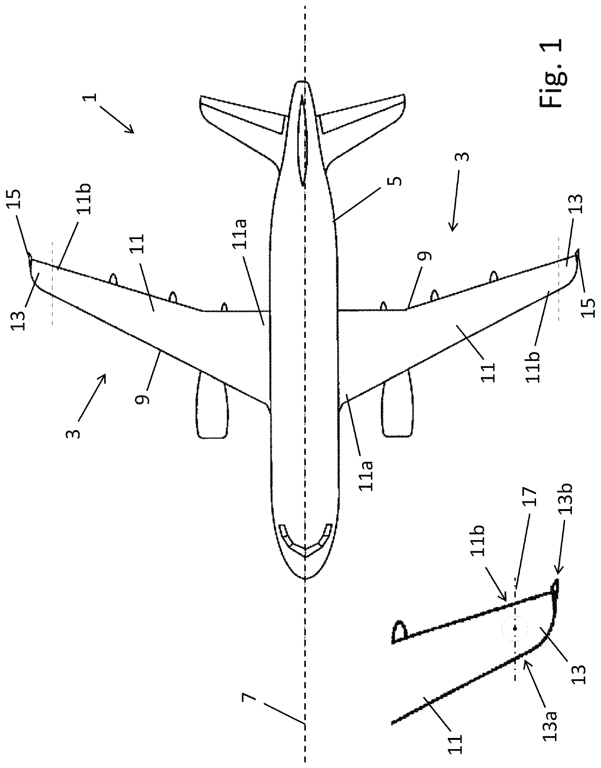
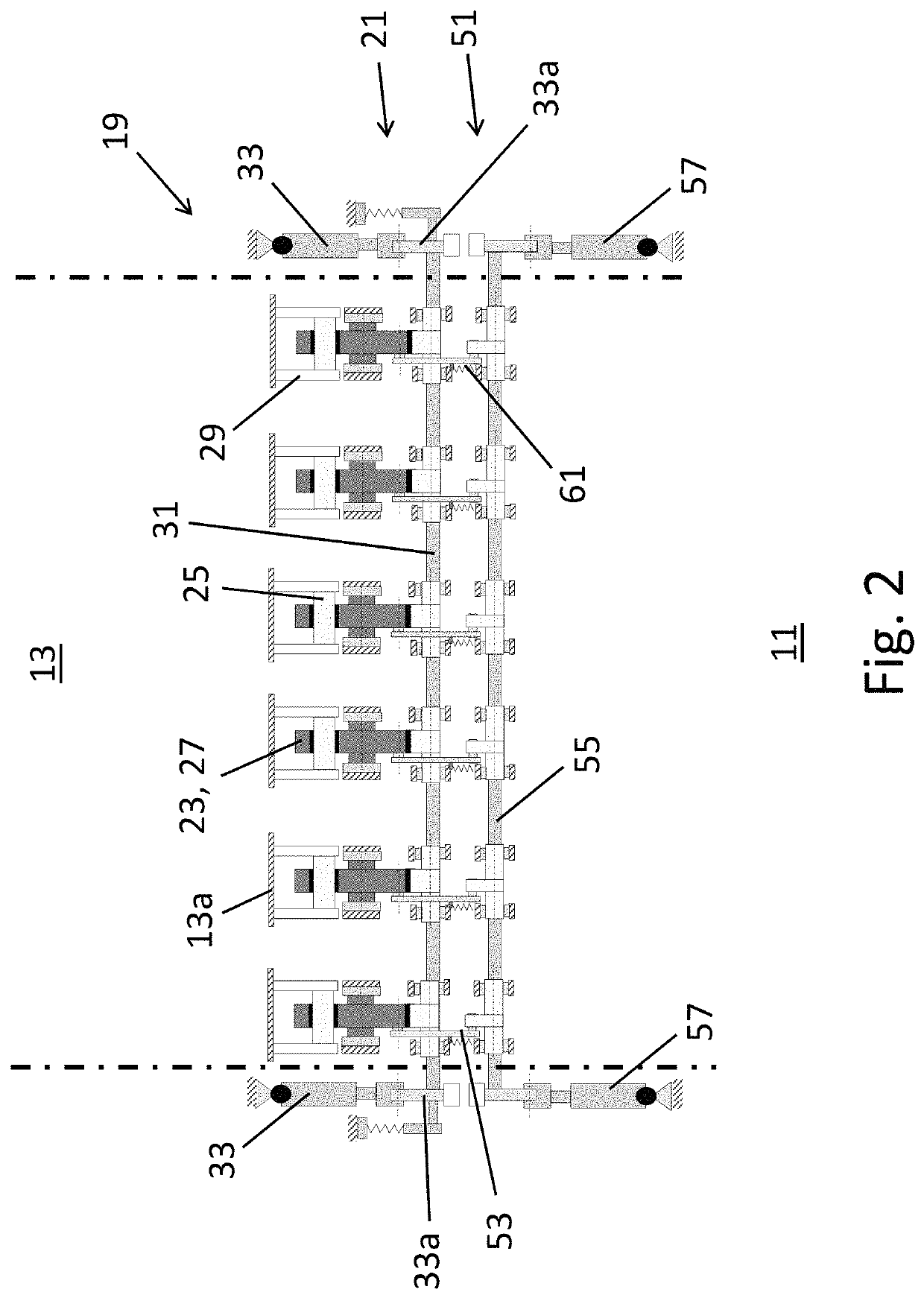
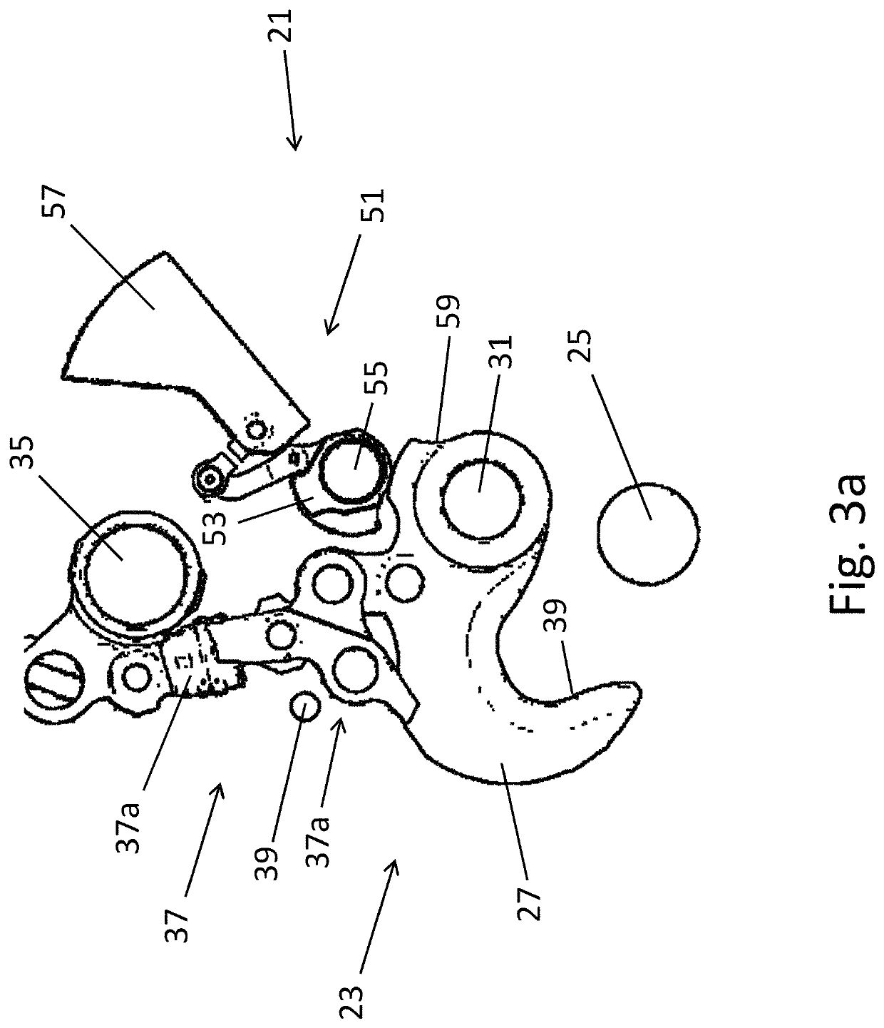
[0043]FIG. 1 shows a schematic top view of an aircraft 1 which comprises two wing arrangements 3 according to the present invention. The aircraft 1 also comprises a fuselage 5 extending along a longitudinal axis 7 which corresponds to the x-axis of the aircraft 1. Each of the wing arrangements 3 comprises a wing 9 that extends away from the fuselage 5, and each wing 9 comprises a base section 11 and a tip section 13. The base section 11 has a first or inboard end portion 11a, which is configured or adapted to be coupled to the fuselage 5 and is shown to be coupled to the fuselage 5, and an opposite second or outboard end portion 11b spaced from the fuselage 5 by the remainder of the base section 11.

[0044]The tip section 13 of the wing 9 is pivotably connected to the second end portion 11b of the base section 11. More particularly, the tip section 13 extends away from the second or outboard end portion 11b of the base section 11 and comprises a third or inboard end portion 13a and an...


PUM


Abstract

A wing arrangement for an aircraft, comprising a wing having a base section and a tip section pivotably connected to base section such that the tip section is pivotable about a pivot axis between a deployed position and a stowed position. The wing arrangement also comprises a latching arrangement which includes an engagement portion, a latching actuator selectively movable between a first actuator position and a second actuator position, an elastically deformable structure, and a latching element. When the tip section is pivoted from the stowed or deployed position into an engagement position, the elastically deformable structure is initially deformed, and as the tip section pivots further into the deployed or stowed position, the elastic deformation of the elastically deformable structure decreases.

Description

CROSS-REFERENCES TO RELATED APPLICATIONS[0001]This application claims the benefit of the European patent application No. 17171842.2 filed on May 18, 2017, the entire disclosures of which are incorporated herein by way of reference.BACKGROUND OF THE INVENTION[0002]The present invention relates to a wing arrangement for an aircraft comprising a wing having a base section with a first end portion and an opposite second end portion, wherein the first end portion is adapted to be secured to the fuselage of an aircraft, and a tip section having a third end portion and an opposite fourth end portion, wherein the third end portion is pivotably connected to the second end portion such that the tip section is pivotable about a pivot axis between a deployed position and a stowed position in which the spanwise length of the wing is smaller than in the deployed position.[0003]The aspect ratio, i.e., the ratio of span to chord, of an aircraft wing is one factor influencing the efficiency of the a...

Claims


Application Information

Patent Timeline
Patent Type & Authority Patents(United States)
IPC IPC(8): B64C3/54B64C3/56F16B45/02
CPCB64C3/546B64C3/56F16B45/02Y02T50/10F16B45/034
Inventor WINKELMANN, CHRISTOPHELLMERS, WILFRIEDBRIANCOURT, STEPHENBRAKES, DAVID
Owner AIRBUS OPERATIONS LTD
Learn More