
Dynamic backrest construction

a backrest and dynamic technology, applied in the direction of seating furniture, stools,ambulance services, etc., can solve the problems of affecting the normal use of care personnel, and the size of gas springs that are only optimally suited, so as to achieve less viscosity

Active Publication Date: 2021-05-04
R82 AS
View PDF14 Cites 0 Cited by
  • Summary
  • Abstract
  • Description
  • Claims
  • Application Information

AI Technical Summary

Benefits of technology

[0018]This resilient back-rest dampening mechanism is completely independent from the hinges and the rest of the chair construction but is connected to the back-rest and to a base such that any forces deriving from movement of the back-rest relative to the seat will be transferred to the base. Typically, the base will be the sub-structure for example of a wheel chair or may even be the seat in certain constructions. With this mechanism it is possible to use ordinary hinges. This facilitates a number of advantages. Particularly, within the technical field of wheel chairs or similar devices for use in the health sector, the requirements to hygiene, safety and handling are very high and often require extensive testing etc. By being able to use already approved parts such as for example hinges which is a very important part of a seat construction particularly in a wheel chair or a car seat, it becomes easier and less costly to provide constructions having the facility of a resilient back-rest dampening mechanism as this is not integrated in other constructional parts of the device in which it is desirable to have the resilient back-rest dampening mechanism.
[0046]Therefore, by using gas or hydraulic springs, the characteristics of the resilient dampening mechanism can be designed very precisely.

Problems solved by technology

Therefore a certain size of gas spring (a certain tension) will only be optimally suited for the seat for a limited period of time.
Although this system works well and does provide for adjustment possibilities of the resilient force, it has a number of drawbacks, one of these being the fact that in order to alter the resilient force it is necessary to adjust the mechanism (move the end of the resilient gas spring along the rail (arm)) in both hinges.
It has proven difficult for the care personnel handling this during normal use, particularly to adjust the resilient force evenly in both hinges.
Consequently in use there will be an uneven application of load to the hinges and thereby the entire seat construction, which may cause failure due to overload or the like.
A further drawback has proven to be the replacement of the gas spring.
Although it is contemplated that this may take place in situ, i.e. in the institution where the seating construction is being used (for example in wheel chairs) this has proven to be a challenge, resulting in using the system with wrong settings thereby not achieving the advantages and benefits of the system.
A still further drawback is the relatively expensive construction.

Method used


Image

  • Dynamic backrest construction
  • Dynamic backrest construction
  • Dynamic backrest construction

Examples


Embodiment Construction

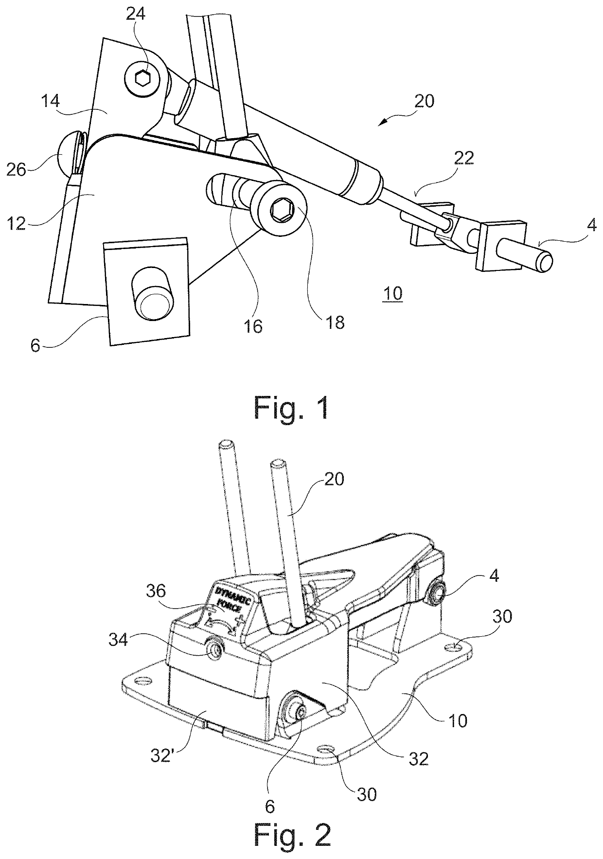
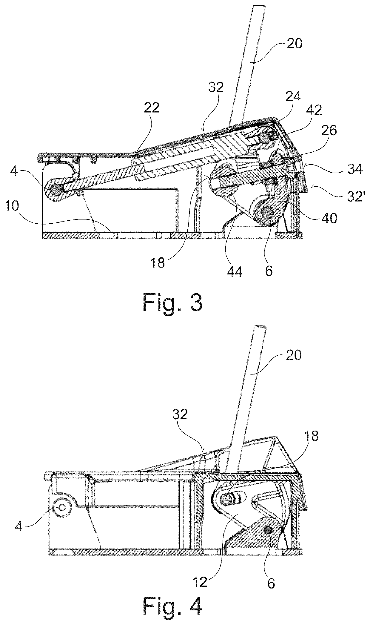
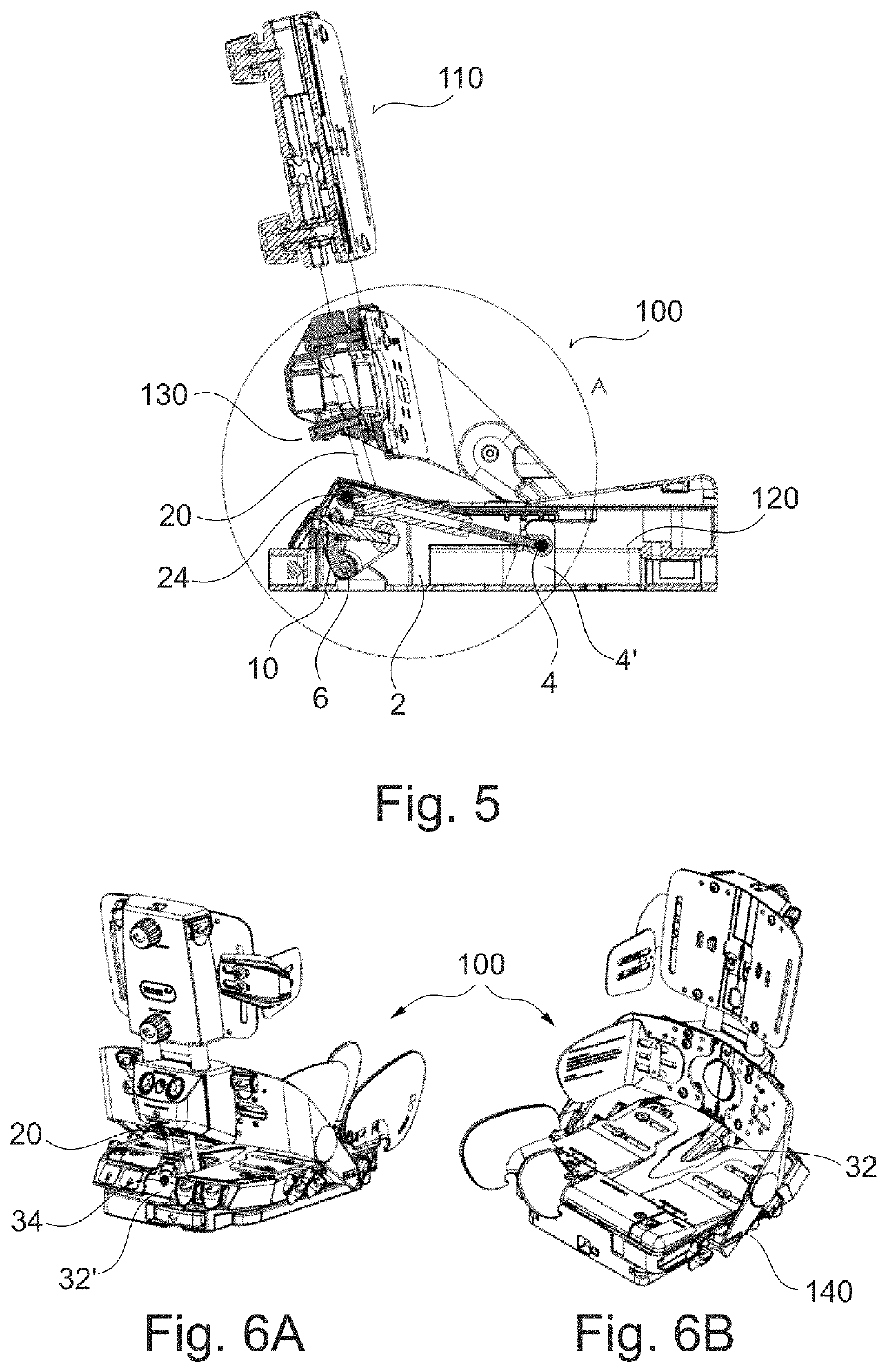
[0053]In FIG. 1 is illustrated the concept of the present invention. The mechanism 1 is arranged on a base 10. On the base is arranged two fastenings creating a first pivot point 4 and a second pivot point 6. The second pivot point is connected to a bracket 12 such that the bracket may pivot relative to the second pivot point and thereby to the base 10. In the bracket 12 is provided a sub-bracket 14 as well as an aperture 16. In the aperture 16 is provided a third pivot point 18. The third pivot point is connected to back-rest connection means 20 which in a first end is connected to the third pivot point and in an opposite end (not illustrated) is releasably and / or adjustably connected to a back-rest. Turning back to the sub-bracket 14, a fourth pivot point 24 is provided such that a resilient member 22 may be connected between the first pivot point 4 and the fourth pivot point 24.

[0054]The sub-bracket 14 is arranged in the bracket 12 such that it may slide whereby the distance betw...


PUM


Abstract

A resilient backrest dampening mechanism is provided for use with chairs having a seat and a backrest, the mechanism comprising four pivot points; a first pivot point arranged on a base different from the backrest; a second pivot point arranged at a distance from the first pivot point on the base, wherein a bracket is pivotally connected to the second pivot point; a third pivot point provided between the bracket and a first end of a backrest connection member, and the backrest connection member being adjustably connected to the backrest; a fourth pivot point provided in the bracket; a resilient member arranged between the fourth pivot point and the first pivot point, and wherein all the pivot points pivot around corresponding axes and all of the axes are parallel.

Description

CROSS-REFERENCE TO RELATED APPLICATION[0001]This application claims the benefit of and priority to DK Application No. PA 2018 70664, filed Oct. 10, 2018. The entire specification and figures of the above-referenced application is hereby incorporated in its entirety by reference.FIELD OF THE INVENTION[0002]The present invention relates to a dynamic backrest construction for seats in general, but particularly to seats or back rests for wheelchairs and a seat or wheelchair with such a dynamic backrest construction.BACKGROUND OF THE INVENTION[0003]For the comfort of disabled persons in wheelchairs it is advantageous to equip the wheelchair with a seat having a dynamic reclinable backrest that is capable of absorbing the energy of sudden and forceful voluntary or involuntary movements of the person against the backrest.[0004]The backrest shall also for therapeutic reasons be resilient such that users with a tendency to spasms, sudden uncontrolled movements etc. are not injured when using...

Claims


Application Information

Patent Timeline
Patent Type & Authority Patents(United States)
IPC IPC(8): A47C7/44A61G5/10
CPCA47C7/446A47C7/441A47C7/448A61G5/1067A61G5/1081A61G2200/34A61G2203/70A61G5/122
Inventor THEILMANN, RASMUSJENSEN, THOMAS LINDHARDT
Owner R82 AS
Learn More