
Rear partition mounted cooling system

a cooling system and rear partition technology, applied in vehicle heating/cooling devices, vehicle components, transportation and packaging, etc., can solve the problems of increasing the speed of degradation, affecting the performance of equipment, and affecting the operation of equipment, so as to achieve the effect of reducing the damage to equipment stored

Active Publication Date: 2021-04-27
TRINITY INNOVATIVE SOLUTIONS LLC
View PDF46 Cites 0 Cited by
  • Summary
  • Abstract
  • Description
  • Claims
  • Application Information

AI Technical Summary

Benefits of technology

[0007]This rear partition mounted cooling system circulates the cooler air or air currents into the cargo area and thereby cools off any equipment enclosed or stored inside the cargo area. Much of the equipment can be sensitive to heat and will degrade in performance or cease working altogether if the internal components of the equipment exceed a specific heat threshold. The circulated air or air currents cools the equipment by directing air or air currents toward the equipment, or in certain embodiments a vacuum effect that pulls warm or heated air or air currents away from the equipment. In addition, the circulated air or air currents push excess heat away from the equipment and can result in an increase in the equipment's efficiency, thereby maintaining the performance of the equipment and increasing the longevity of it as well. The equipment's components degrade over time, and successive overheating increases the speed of degradation as well as decreasing the operational shelf life of the equipment. Decreasing the successive strain from overheating prolongs the usefulness of the equipment and ensures that it continues to work properly.
[0008]The system can be engaged automatically or manually by the user. End users of the equipment may be away from the vehicle with the equipment actively operating while stored in the cargo area. The equipment needs to be ready to function at the moment that the user requires and the user may not have time to wait for the equipment to cool off. Thus, the equipment needs to be continuously cooled by the fan system while the user is away from the vehicle. By having the system function on its own, the equipment can continue to stay cool and functional even if the user is incapable of monitoring the condition of the equipment before use.
[0011]In addition, various modifications can be made to the fan system depending on the sensitivity of the equipment in the cargo area. The modifications can be used by themselves or combined with others. For instance, a filter can be installed to the system to filter out the air if there is a concern that harmful particles will be circulated from the passenger area into the equipment. In addition, if there is a concern about humidity damaging the equipment, a desiccant can be inserted to help lower the humidity of the air that the rear partition mounted cooling system circulates into the cargo area.
[0013]In another aspect, the present disclosure is directed to a system with an integrated controller module that can engage the fan system without manual input by a user so that the system can be running even if the user is not around the vehicle to turn it on or is incapable of turning it on at the desired moment in time.
[0015]In still another aspect, the present disclosure is directed to a set of modifications that can be inserted to mitigate harm to equipment stored in the cargo enclosure from harmful air particles, the presence of humidity, or similar environmental hazards.

Problems solved by technology

Much of the equipment can be sensitive to heat and will degrade in performance or cease working altogether if the internal components of the equipment exceed a specific heat threshold.
The equipment's components degrade over time, and successive overheating increases the speed of degradation as well as decreasing the operational shelf life of the equipment.

Method used


Image

  • Rear partition mounted cooling system
  • Rear partition mounted cooling system
  • Rear partition mounted cooling system

Examples


Embodiment Construction

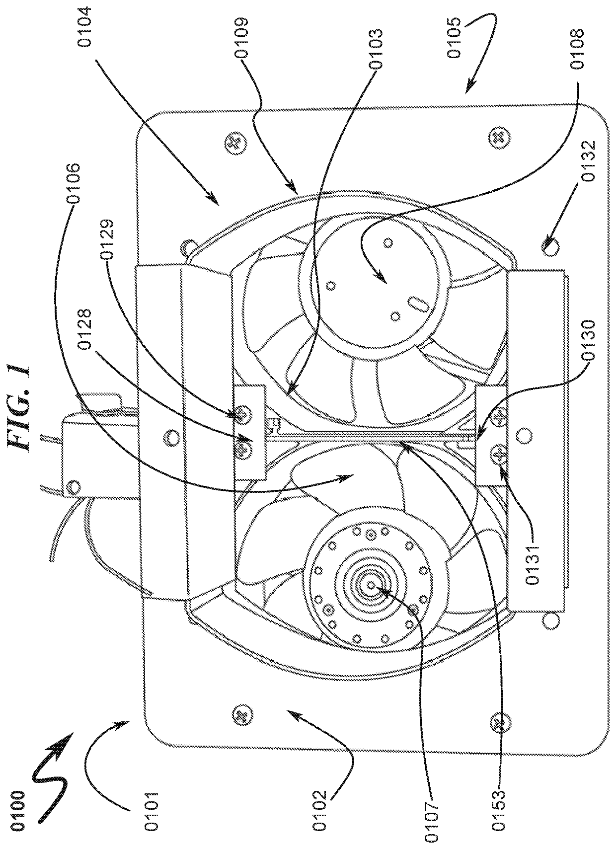
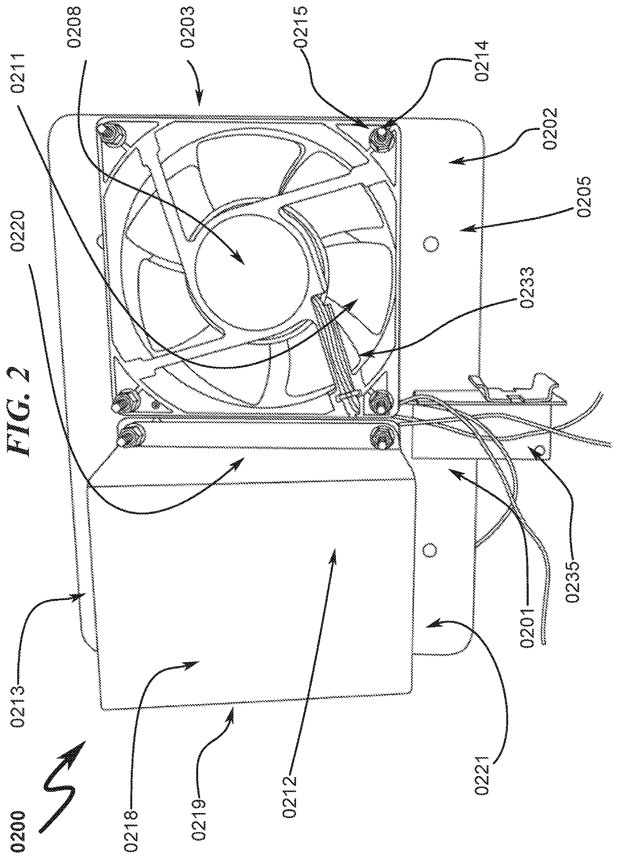
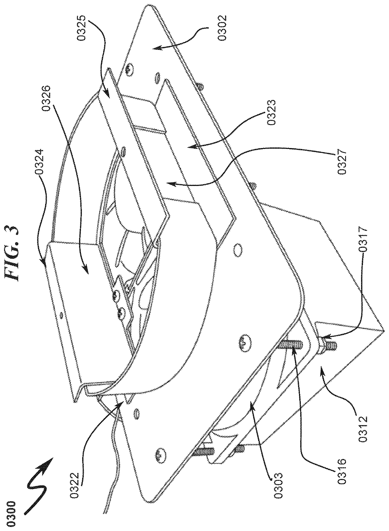
[0029]An exemplary embodiment of the invention will now be described. Now referring in general to FIG. 1, set forth is a top view 0100 of an embodiment of the present disclosure 0101 that is an environmental control apparatus for use in a vehicle having a cargo area and an environmentally controlled passenger area with a deck or partition between the passenger and cargo areas. The apparatus of the exemplary embodiment of the present disclosure having a mounting plate 0102 and a fan unit 0103 that includes at least one fan. The fan unit(s) 0103 having at least one motor corresponding to the at least one fan(s). The mounting plate is constructed of any rigid material and has an upper surface 0104 and a lower surface 0205, which is further illustrated in FIG. 2. In the center of the mounting plate 0102 is a large centrally located aperture 0106. The fan unit 0103 has illustrated in the exemplary embodiment a first fan 0107 and a second fan 0108, which are located underneath the lower s...


PUM


Abstract

The disclosure describes a system and method for the environmental control of a vehicle having a cargo area and an environmentally controlled passenger area with a partition between the passenger area and the cargo area. The environmental control being directed and performed by an environmental control unit that can include one or more fans, a control module, a mounting plate, and a directional manifold to control the direction of the airflow. The environmental control unit can be installed using a method that includes attaching a fan unit to the mounting plate, connecting the fan unit to the control module, coupling to the fan unit and / or the control module to a power supply, and attaching a directional manifold to control the direction of airflow in or out of the fan unit.

Description

BACKGROUND OF THE INVENTIONTechnical Field[0001]The present disclosure relates to vehicles, and internal fan systems for vehicles. More particularly, and not by way of limitation, the present disclosure is directed to a system and method for circulating air from the passenger area of a vehicle into the cargo area of a vehicle to cool and dissipate heat generated by sensitive electronic equipment stored in the cargo area while in use. Additionally, the present disclosure is directed to the exchange of air from two areas of different temperatures, accordingly it can move higher temperature air to an area with a lower temperature or move lower temperature air to an area with a higher temperature.Description of Related Art[0002]Vehicles have become an indispensable tool for law enforcement and security personnel. Vehicles can be, but are not limited to, cars, trucks, vans, cargo containers, trains, airplanes, or ships. This includes not only getting personnel to distant locations quickl...

Claims


Application Information

Patent Timeline
Patent Type & Authority Patents(United States)
IPC IPC(8): B60H1/00B60H3/02B60H3/06
CPCB60H1/00271B60H1/00414B60H1/00564B60H1/00885B60H3/024B60H3/0658B60H2001/003
Inventor HARMS, DWIGHT DAVIDHALL, TIMOTHY FRANCIS
Owner TRINITY INNOVATIVE SOLUTIONS LLC
Learn More