
Method for antenna selection for concurrent independent transmissions via multiple antennas

a technology of independent transmission and antenna selection, applied in the direction of antennas, antenna details, basic electric elements, etc., can solve the problems of reducing the range and/or throughput on the transmission path, spurious emissions levels above, and affecting the overall data transfer throughpu

Active Publication Date: 2021-04-06
MOTOROLA MOBILITY LLC
View PDF6 Cites 5 Cited by
  • Summary
  • Abstract
  • Description
  • Claims
  • Application Information

AI Technical Summary

Benefits of technology

The present disclosure provides a communication device, method, and computer program product that optimizes performance by multiple transmitters by selecting antennas that minimize intermodulation distortion (IMD) caused by concurrent transmissions. The device includes a first transmitter that transmits at a first frequency and a first antenna that radiates a first transmit signal at a first TRP. A second transmitter of the device generates a second transmit signal at a second frequency. The second antenna has a second efficiency rating that yields a second TRP. The device also includes at least one alternate second antenna that has an alternate second efficiency rating that yields an alternate second TRP. The controller monitors the concurrent communication activity of the first and second transmitters and the at least one receiver and identifies the transmit power limits associated with IMD for the first and second antennas based on the first antenna isolation. The technical effect of the patent is to minimize intermodulation distortion and spurious emissions levels above standards while optimizing performance by multiple transmitters.

Problems solved by technology

However, the simultaneous transmission by multiple transmitters gives rise to negative interactions that include: (i) intermodulation distortion (IMD) products between transmitters that fall in active receive bands, causing self-desensitization that results in degradation of overall data transfer throughput; (ii) IMD products between transmitters that fall outside of receive bands of the communication device but result in spurious emissions levels above those permissible by standards bodies for maximum sensitivity degradation (MSD) and other communication regulations; and (iii) radio frequency (RF) radiation exposure to a human body that is above a regulatory limit.
Transmit power reduction has the negative consequence of reducing Total Radiated Power (TRP) and therefore reduces range and / or throughput on that transmission path.

Method used


Image

  • Method for antenna selection for concurrent independent transmissions via multiple antennas
  • Method for antenna selection for concurrent independent transmissions via multiple antennas
  • Method for antenna selection for concurrent independent transmissions via multiple antennas

Examples


Embodiment Construction

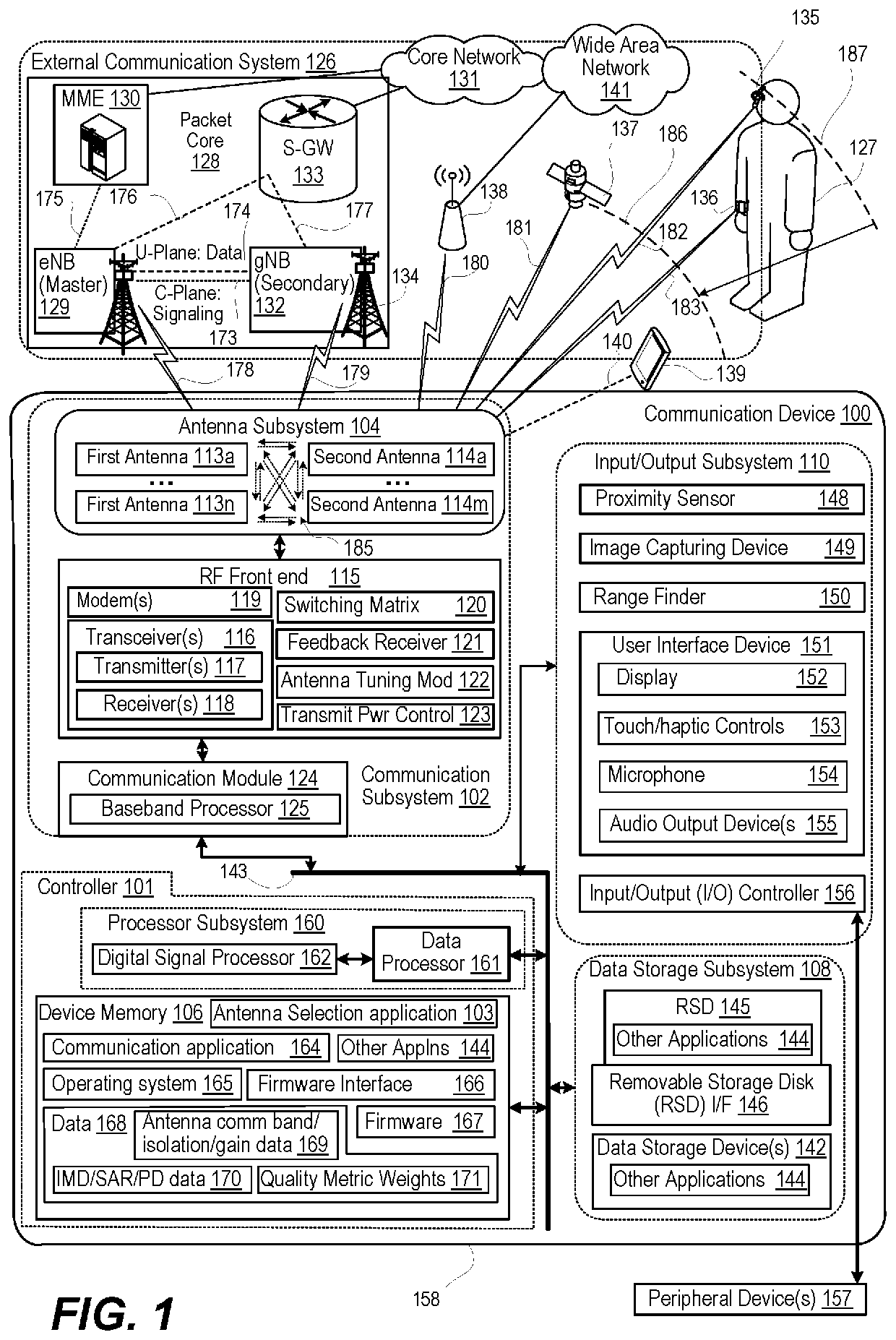
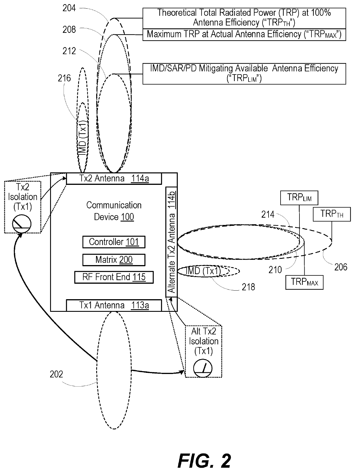
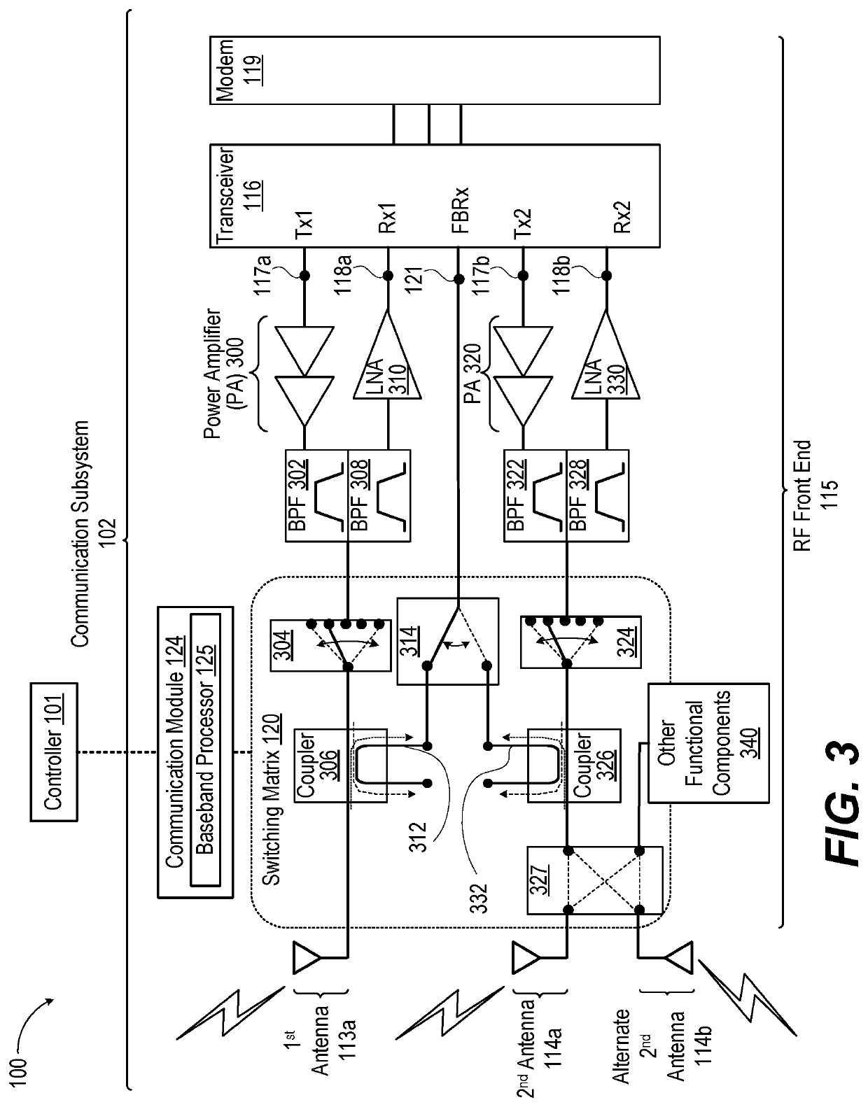
[0010]According to aspects of the present disclosure, a communication device, method, and computer program product provide for antenna selection that optimizes performance by multiple transmitters. In one or more embodiments, the communication device includes a first transmitter that transmits at a first frequency. The communication device includes a first antenna electrically coupled to the first transmitter. The first antenna radiates a first transmit signal at a first total radiated power (TRP). A second transmitter of the communication device generates a second transmit signal at a second frequency. The second antenna has a second antenna efficiency rating (gain) at the second transmit frequency that yields a second TRP. The second antenna has a first antenna isolation level transmitting at the second transmit frequency to the first antenna transmitting at the first frequency The communication device includes at least one alternate second antenna, each having an alternate second...


PUM


Abstract

A communication device has a controller that selects one of a second antenna and at least one alternate second antenna for concurrent transmission with a first antenna. The controller monitors concurrent communication activity of the first and the second transmitter. Based on the concurrent communication activity, the controller identifies respective transmit power limits associated with intermodulation distortion (IMD) for the first antenna transmitting at the first transmit frequency and one of the second antenna and the at least one alternate second antenna transmitting at the second transmit frequency and having respective antenna isolation levels to the first antenna. The controller identifies, available total radiated power (TRP), respectively, for the second antenna and the at least one alternate second antenna and connects the second transmitter to one of the second antenna and the at least one alternate second antenna having the highest available TRP to optimize communication performance.

Description

TECHNICAL FIELD[0001]The present disclosure relates generally to communication devices and methods for concurrent transmission on closely positioned antennas, and more particularly to communication devices and methods for mitigating intermodulation distortion (IMD) caused by concurrent transmission.DESCRIPTION OF THE RELATED ART[0002]Developments in communication devices increasingly include concurrent transmission via antennas that are in close proximity. For example, in moving from fourth generation long term evolved (LTE) radio access technology (RAT) to fifth generation new radio (5G NR) RAT, communication devices typically have seen an increase in a number of transmit paths that operate simultaneously. A typical LTE communication device has a maximum of two transmitters that are simultaneously active, one LTE transmitter and one Wi-Fi transmitter. A 5G NR communication device can have up to two 5G NR transmitters in multiple input multiple output (MIMO) operation, one LTE trans...

Claims


Application Information

Patent Timeline
IPC IPC(8): H04B1/525H04B1/10H04B3/52H01Q21/28H01Q1/24H04B1/18
CPCH04B1/525H01Q1/243H01Q21/28H04B1/109H04B1/18H04B3/52H04B1/0064H04B1/48H01Q1/245H01Q1/2291
Inventor KLOMSDORF, ARMINSCHWENT, DALEBREMER, BRIAN H.
Owner MOTOROLA MOBILITY LLC
Learn More