
Gear train unit and arrangement for a stamping press

a gear train and stamping press technology, applied in the direction of gearings, press rams, transmission elements, etc., can solve the problems of unnecessary limitation of the power which can be transmitted with the gear, and the use of very expensive components made of highly rigid materials

Active Publication Date: 2021-03-30
BRUDERER ARBON SCHWEIZ
View PDF11 Cites 3 Cited by
  • Summary
  • Abstract
  • Description
  • Claims
  • Application Information

AI Technical Summary

Benefits of technology

The invention is a gear train unit that has multiple stages connected one after the other, which is cost-effective, strong, and compact. It can transfer high powers. In an optional embodiment, the gear train unit is surrounded by a drum-shaped housing that acts as the output of the gear train. This makes the installation process more compact.

Problems solved by technology

However, this gear train unit has the disadvantage that different components of the gear, e.g. the driving element, are subjected to extreme mechanical stress during operation due to the construction of the gear, thus making it necessary to use very expensive components made of highly rigid materials and leading to an unnecessary limitation of the powers which can be transmitted with the gear.

Method used


Image

  • Gear train unit and arrangement for a stamping press
  • Gear train unit and arrangement for a stamping press
  • Gear train unit and arrangement for a stamping press

Examples


Embodiment Construction

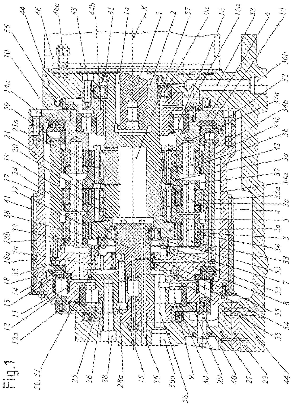
[0042]FIGS. 1 and 2 show a switchable gear train unit according to the invention with three planetary gear train stages connected one after the other in vertical longitudinal section, once in a switching state in which the gear is effective (FIG. 1) and once in a state in which the gear is locked (FIG. 2), i.e. in which the transmission ratio is 1:1.

[0043]The illustrations according to FIGS. 3 and 4 show an arrangement according to the invention with the gear train unit of FIGS. 1 and 2 and a punching press 47 driven by it, once in a partial rear view (FIG. 3) with the so-called main drive and one in a partial side view (FIG. 4) with the motor mount.

[0044]As can be seen, the gear train unit has a central driving element 2 which is coupled at one of its ends to a horizontally lying shaft 1 of an electric motor 46 (shown in FIGS. 3 and 4) and which forms at its other end the sun gear 2a of the first planetary gear train stage. When operated as intended the electric motor 46 drives, vi...


PUM


Abstract

The invention relates to a gear train unit, comprising a plurality of planetary gear train stages, which are connected one after the other and which each comprise a ring gear, a sun gear, and a plurality of planet gears supported on a planet carrier, wherein the sun gear of each following planetary gear train stage is formed by the planet carrier of the preceding planetary gear train stage. The gear train unit comprises a driving element, which forms the sun gear of the first planetary gear train stage, and an output element, which forms the planet carrier of the last of the gear planetary gear train stages connected one after the other. The driving element is supported by means of first bearings arranged in the region of ends of the driving element, in such a way that the driving element can rotate about a longitudinal axis of the driving element, and at least some of the planet carriers of the planetary gear train stages are supported on the driving element in the region between the first bearings by means of bearings. The invention makes it possible to provide a gear train unit having a plurality of planetary gear train stages connected one after the other that is economical, extremely robust, and very compact and that additionally can transmit very high power.

Description

CROSS REFERENCE TO RELATED APPLICATION[0001]Applicant hereby claims priority benefits under U.S.C. § 119 from International Patent Application Serial No. PCT / CH2013 / 000193, filed on Nov. 6, 2013, the contents of which are incorporated by reference herein.TECHNICAL FIELD OF THE INVENTION[0002]The present invention relates to a gear train unit with a plurality of planetary gear train stages which are connected one after the other as well as an arrangement comprising such a gear train unit according to the preambles of the independent claims.[0003]Gear train stages with a plurality of planetary gear train stages connected one after the other are used in cases where extremely high torques are required at low rotational speeds.[0004]A gear train stage according to this type, with three planetary gear train stages for driving punching presses is known from EP 2 375 102 A1. However, this gear train unit has the disadvantage that different components of the gear, e.g. the driving element, a...

Claims


Application Information

Patent Timeline
Patent Type & Authority Patents(United States)
IPC IPC(8): F16H3/64B30B1/26F16H37/02
CPCF16H3/64B30B1/266F16H37/02F16H2200/0034F16H2200/201F16H3/66
Inventor HAFNER, JOSEF THOMASHARDMEIER, PASCAL
Owner BRUDERER ARBON SCHWEIZ
Learn More