Ceiling type seismic impact buffer unit

a buffer unit and floor technology, applied in the direction of vibration suppression adjustment, mechanical equipment, wound springs, etc., can solve the problems of accidents or loss of lives

Active Publication Date: 2021-03-30
LEE AN SE
View PDF24 Cites 1 Cited by
  • Summary
  • Abstract
  • Description
  • Claims
  • Application Information

AI Technical Summary

Benefits of technology

[0009]Therefore, the present invention has been made in view of the above problems, and it is an object of the present invention to provide a ceiling type seismic impact buffer unit which connects an upper connection rod vertically coupled to an anchor bolt of a ceiling slab, and a lower connection rod coupled to a ceiling panel so as to hang the ceiling panel attached thereto to support the ceiling panel, so that the ceiling type seismic impact buffer unit performs a buffering action, and thus, even if vibration or strong impact attributable to natural disasters, such as earthquakes or typhoons, is applied to a building and the vibration or the impact is transmitted to the upper connection rod vertically coupled to the anchor bolt of the ceiling slab, allows the lower connection rod coupled to the ceiling panel to prevent ceiling structures installed on the ceiling panel from being separated from the ceiling panel or damaged through the buffering action of reducing the vibration or the impact.

Problems solved by technology

However, since the ceiling panel is supported by the connection rod connected to the anchor bolt of the ceiling slab and is thereby vertically fixed, if vibration or strong impact attributable to natural disasters, such as earthquakes or typhoons, is applied to a building, the vibration or the impact is applied to the ceiling panel fixed to the ceiling, the ceiling panel is strongly shaken in the lateral direction, and ceiling structures installed on the ceiling panel are separated from the ceiling panel or damaged and thus fall on the indoor floor, thereby causing danger of accidents or loss of lives.

Method used


Image

  • Ceiling type seismic impact buffer unit
  • Ceiling type seismic impact buffer unit
  • Ceiling type seismic impact buffer unit

Examples


Embodiment Construction

[0021]Hereinafter, reference will now be made in detail to the preferred embodiments of the present invention, examples of which are illustrated in the accompanying drawings. In the following description of the present invention, a detailed description of known functions and configurations incorporated herein will be omitted when it may make the subject matter of the present invention rather unclear.

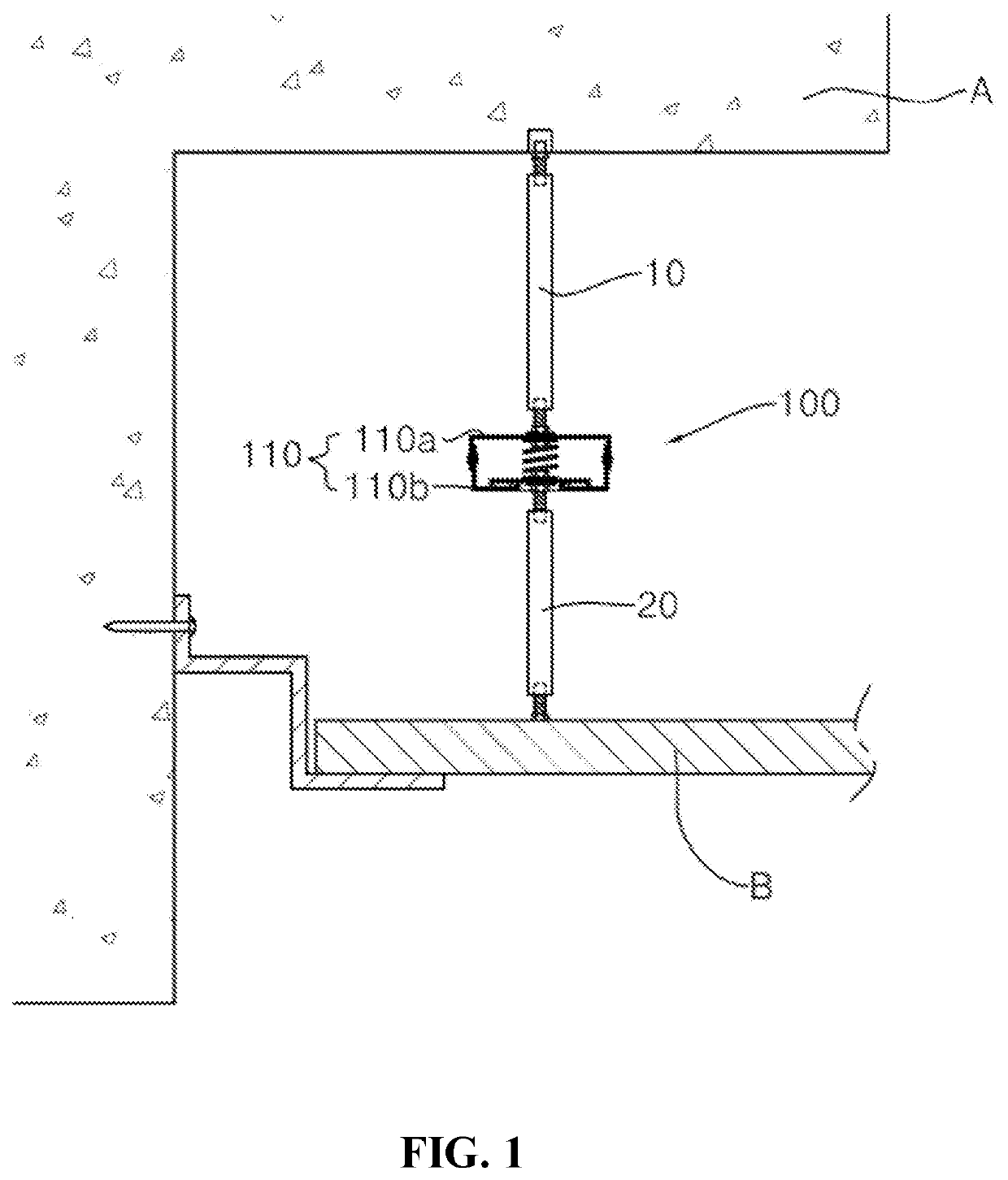
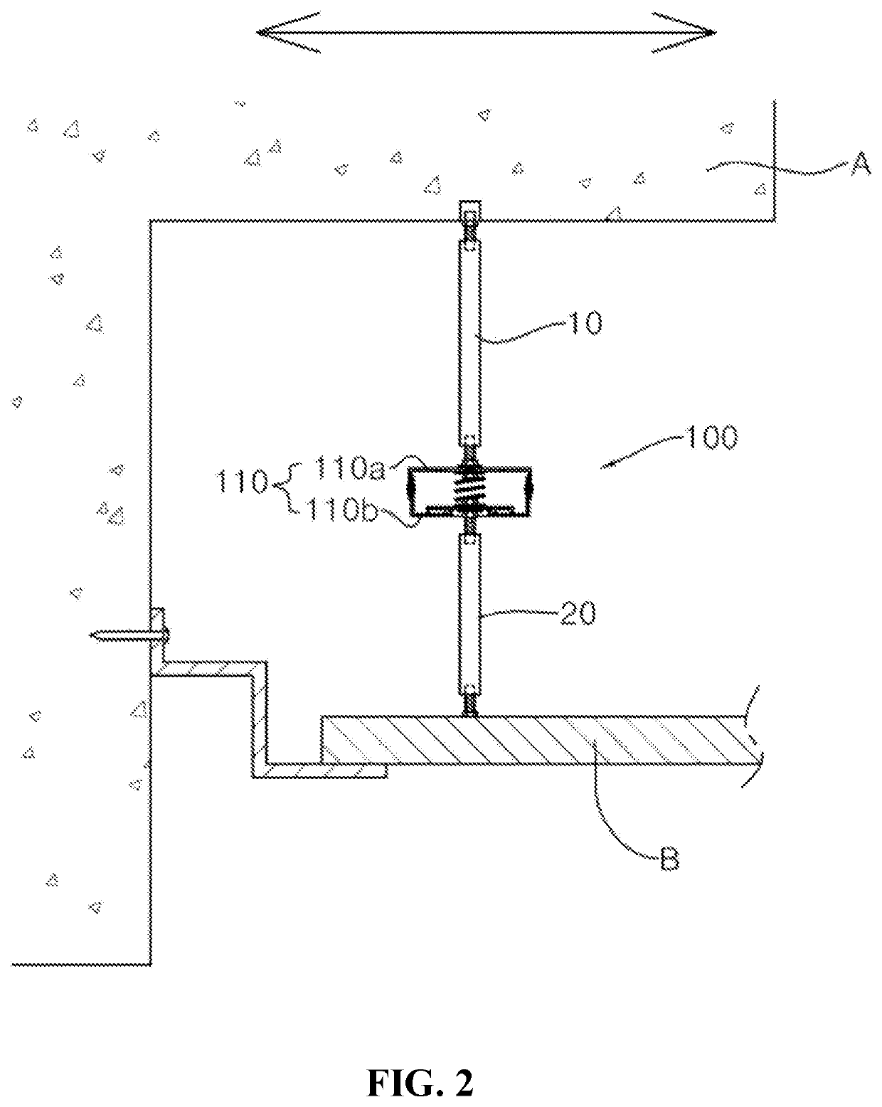
[0022]In the present invention, an upper connection rod 10 is vertically coupled to an anchor bolt of a ceiling slab A, a ceiling panel B is coupled to a lower connection rod 20 so as to be hung thereon to be supported, and the upper and lower connection rods 10 and 20 are connected to each other by a ceiling type seismic impact buffer unit 100 so that the ceiling type seismic impact buffer unit 100 performs an action of buffering the impact applied to the ceiling panel B.

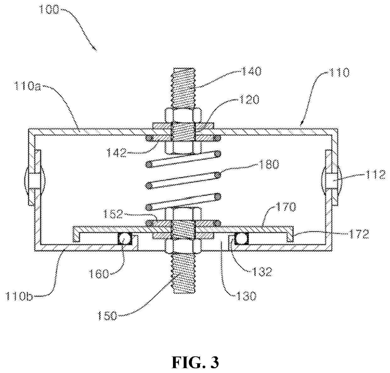
[0023]The ceiling type seismic impact buffer unit 100 includes a housing main body 110 which includes upper and lower...


PUM


Abstract

Disclosed is a ceiling type seismic impact buffer unit which may perform a buffering action of reducing vibration or the impact applied thereto attributable to earthquakes, typhoons, etc. without direct transmission of the vibration or the impact to a ceiling panel installed on a ceiling. The ceiling type seismic impact buffer unit includes a housing main body, a first coupling bolt, which is fixed into a coupling hole formed in the center of the upper surface of the housing main body and has a front end connected to an upper connection rod, a second coupling bolt, which is fixed to a sliding contactor through a sliding guide hole formed in the center of the lower surface of the housing main body and has a front end connected to a lower connection rod, and a restoring spring, which has upper and lower ends coupled to first and second fixing washers.

Description

BACKGROUND OF THE INVENTIONField of the Invention[0001]The present invention relates to a ceiling type seismic impact buffer unit, and more particularly to a ceiling type seismic impact buffer unit which, even when vibration or impact is applied to a building attributable to earthquakes, typhoons, etc., may reduce the vibration or the impact without direct transmission of the vibration or the impact to a ceiling panel installed on a ceiling so as to maintain the firmly fixed state of a ceiling structure and to prevent damage to the ceiling structure through such a buffering action.Description of the Related Art[0002]In general, a plurality of ceiling panels is constructed to shield the ceiling of a building so as to hide the poor appearance of the ceiling on which various structures, such as various wires, ventilation ducts, etc., are installed due to electric works, or a ceiling panel configured to shield the ceiling is installed to prevent contaminated air from the outside from be...

Claims


Application Information

Patent Timeline
Patent Type & Authority Patents(United States)
IPC IPC(8): E04H9/02E04B9/04E04B9/18F16F15/067E04B9/20E04B9/24E04B9/30
CPCE04H9/0215E04B9/04E04B9/18E04B9/20F16F15/067E04B9/241E04B9/30E04B2009/186E04H9/021F16F2236/103F16F2238/026
Inventor LEE, AN SE
Owner LEE AN SE
Why Eureka
Try Eureka