Brake system component axle mount

a technology for brake system components and axle mounts, which is applied in braking systems, curtain suspension devices, manufacturing tools, etc., can solve problems such as reducing the life expectancy of axles, creating significant stress risers, and local mechanical property changes in axles

Active Publication Date: 2021-03-23
HENDRICKSON USA L L C
View PDF20 Cites 0 Cited by
  • Summary
  • Abstract
  • Description
  • Claims
  • Application Information

AI Technical Summary

Benefits of technology

[0008]Objectives of the present invention include providing a brake system component axle mount that eliminates all of the welds between the mount and the axle of the axle / suspension system.
[0009]Yet another objective of the present invention is to provide a brake system component axle mount that improves the life and durability of the brake mount connection.

Problems solved by technology

More specifically, the welding of the brake chamber bracket and the cam shaft bracket directly to the axle can potentially create significant stress risers and local mechanical property changes in the axle, as is generally well known in the art.
These stress risers and local mechanical property changes in the axle can in turn potentially reduce the life expectancy of the axle.

Method used


Image

  • Brake system component axle mount
  • Brake system component axle mount
  • Brake system component axle mount

Examples


Embodiment Construction

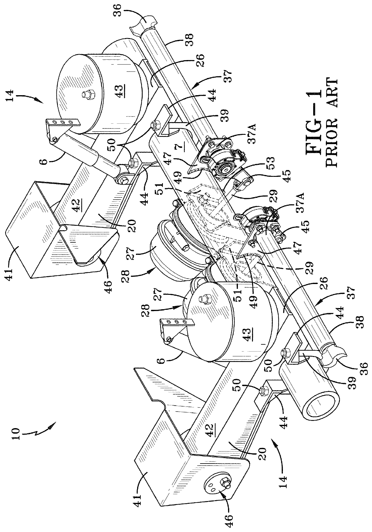
[0025]A prior art trailing arm overslung beam-type air-ride axle / suspension system for heavy-duty vehicles is indicated generally at 10, is shown in FIG. 1, and now will be described.

[0026]Because axle / suspension system 10 includes a pair of suspension assemblies 14 that generally mirror one another, for sake of clarity only one of the suspension assemblies will be described below.

[0027]Suspension assembly 14 is pivotally connected to a hanger 41 via a trailing arm overslung beam 42. More specifically, trailing arm beam 42 includes a front end 20 having a bushing assembly 46, which includes a bushing, pivot bolts and washers, as are well known in the art, to facilitate pivotal connection of the beam to hanger 41. Beam 42 also includes a rear end 26, which is rigidly attached to a transversely-extending axle 7 via a pair of U-bolts 39 (only one shown) that are disposed around the axle and fastened, via nuts 50, to U-bolt brackets 44, which in turn are mounted on beam 42.

[0028]Suspens...


PUM

PropertyMeasurementUnit
shapeaaaaaaaaaa
adhesiveaaaaaaaaaa
durabilityaaaaaaaaaa

Abstract

A brake system component axle mount for a vehicle axle / suspension system includes an axle having at least one depression formed therein. A sleeve is formed with at least one depression and disposed about the axle so that the axle depression and the sleeve depression matingly engage one another to form a mated pair of depressions. A brake mount assembly is rigidly attached to the sleeve. A method of forming the brake system component axle mount includes providing an axle and disposing a sleeve about the axle. At least one mated pair of depressions is simultaneously formed in the axle and the sleeve. A brake mount assembly is rigidly attached to the sleeve.

Description

CROSS-REFERENCE TO RELATED APPLICATION[0001]This application claims the benefit of U.S. Provisional Patent Application Ser. No. 61 / 388,285, filed Sep. 30, 2010.BACKGROUND OF THE INVENTIONField of the Invention[0002]The invention relates generally to brake systems for wheeled vehicles. More particularly, the invention is directed to the brake component mounting brackets that are attached to or adjacent to the axle of the vehicle. More specifically, the invention is directed to a heavy-duty brake system component axle mount for trucks and tractor-trailers, in which the mounting brackets for the brake system components are securely and efficiently connected to the axle by a brake bracket mounting sleeve. The sleeve and axle structure, together with the manner in which the brake system component axle mount connections are made and assembled, eliminates welds between the mounting brackets and the axle. Elimination of these welds in turn eliminates stress risers and local mechanical prope...

Claims


Application Information

Patent Timeline
Patent Type & Authority Patents(United States)
IPC IPC(8): F16D65/00B23P11/00B60T1/06F16D65/28F16D125/64F16D125/56F16D55/00
CPCB23P11/00B60T1/067F16D65/28B23P2700/14F16D2055/0008F16D2125/56F16D2125/64Y10T29/49826
Inventor FULTON, R. SCOTTWESTNEDGE, ANDREW J.RUBALSKIY, DMITRIY E.KEELER, MICHAEL J.PIERCE, PHILLIPPI R.
Owner HENDRICKSON USA L L C
Why Eureka
Try Eureka