Eureka AIR delivers breakthrough ideas for toughest innovation challenges, trusted by R&D personnel around the world.

Device and method for determining the flow velocity of a fluid in a hollow body

a technology of fluid flow velocity and device, which is applied in the direction of measurement devices, volume/mass flow by dynamic fluid flow effect, instruments, etc., can solve the problems of more difficult and energy-intensive disturbance generation, particularly vortex

Active Publication Date: 2021-03-09
SIKA DR SIEBERT & KÜHN GMBH & CO KG
View PDF9 Cites 0 Cited by
  • Summary
  • Abstract
  • Description
  • Claims
  • Application Information

AI Technical Summary

Benefits of technology

The invention is for a device used in fluid flows to prevent disturbances. The device has a baffle body with a part that creates the disturbance and a sensor to detect it. The baffle body can be adjusted so that the size of the disturbance is variable. This helps to control the flow of the fluid and prevent blockages or other problems.

Problems solved by technology

Naturally, it is more difficult and energy intensive to generate a disturbance, in particular a vortex, that can be detected by the sensor in highly viscous fluids than in liquids with a low viscosity, e.g. water.

Method used


Image

  • Device and method for determining the flow velocity of a fluid in a hollow body
  • Device and method for determining the flow velocity of a fluid in a hollow body
  • Device and method for determining the flow velocity of a fluid in a hollow body

Examples


Embodiment Construction

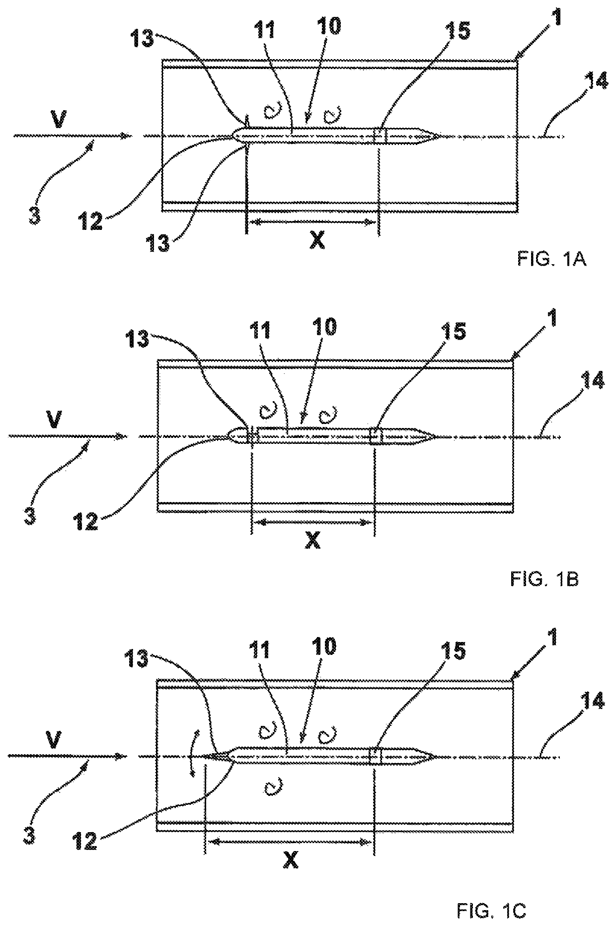
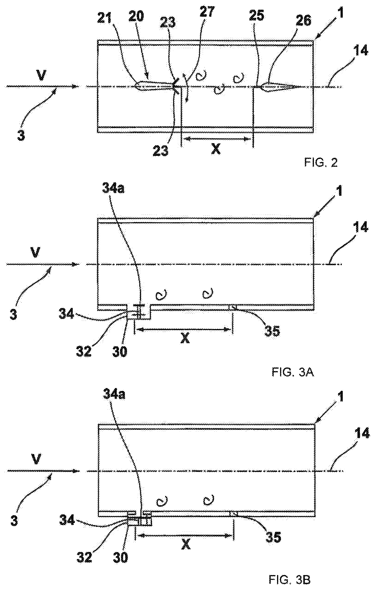
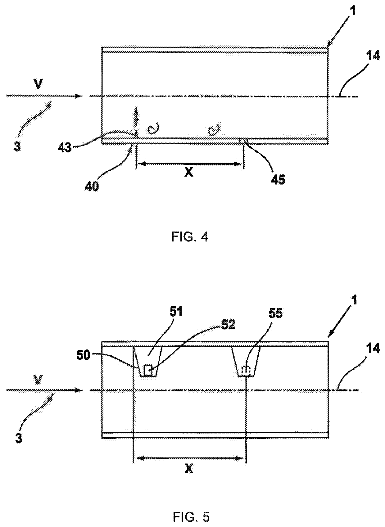
[0026]In FIG. 1A to FIG. 5 the schematically shown hollow body is labeled 1.

[0027]The disturbance device 10 is located inside the hollow body 1 according to FIG. 1A (1st variant). The disturbance device 10 includes the disturbance body 11, wherein the disturbance body 11 comprises respectively one disturbing element 13 on its upper and lower side in the area of its nose 12, which faces the flow (arrow 3). The disturbing element 13 can be continuously extended or swung out of the baffle body 11 transversely to the center longitudinal axis 14, wherein the surface area facing the flow depends on the current extension length. In this respect, the size of the surface area influences the size of the disturbance generated in the fluid, e.g. in the form of an impulse or an impulse sequence.

[0028]The disturbance device 10 with the baffle body 11 includes the sensor 15, disposed at a distance (distance X) from the disturbing element 13, for identifying disturbances generated by the disturbing...


PUM


Abstract

A device and a method for determining the flow velocity of a fluid in a hollow body, including at least one disturbance device disposed in the hollow body and at least one sensor for identifying disturbances that are induced in the flow by the disturbance device, which is disposed at a certain distance downstream in the direction of flow from the disturbance device, wherein the disturbance device includes means for generating changeable disturbances in the fluid flow.

Description

REFERENCE TO RELATED APPLICATION[0001]This application claims priority from German Patent Application No. DE 10 2018 119 805.1, filed Aug. 15, 2018, the entire content of which is incorporated herein by reference.FIELD OF THE DISCLOSURE[0002]The disclosure relates, on the one hand, to a device for determining the flow velocity of a fluid in a hollow body, comprising at least one disturbance device disposed in a hollow body and at least one sensor disposed at a certain distance downstream of the disturbance device in the direction of flow for identifying disturbances, which have been induced in the flow by the disturbance device, as well as, on the other hand, to a method for determining the flow velocity of a fluid in a hollow body.BACKGROUND OF THE DISCLOSURE[0003]Various methods for determining the flow velocity of a fluid or the volumetric flow rate in a hollow body are known from the prior art. For example, a so-called vortex meter, i.e. a vortex flow meter, is known, which has ...

Claims


Application Information

Patent Timeline
Patent Type & Authority Patents(United States)
IPC IPC(8): G01F1/32
CPCG01F1/3227G01F1/3254G01P5/01G01F1/32G01F1/3209G01F1/3259
Inventor WILKE, BASTIAN
Owner SIKA DR SIEBERT & KÜHN GMBH & CO KG
Why Eureka
Eureka Blog
Learn More