
Bumper beam having an 8 shaped cross-section

a technology of bumper beam and cross-section, which is applied in the direction of bumpers, vehicle components, vehicular safety arrangements, etc., can solve the problems that the effort to improve one or the other of these characteristics is generally detrimental to one and/or the other characteristics, and achieve the effect of improving results

Active Publication Date: 2021-03-09
ARCELORMITTAL INVESTIGACION Y DESARROLLO SL
View PDF8 Cites 0 Cited by
  • Summary
  • Abstract
  • Description
  • Claims
  • Application Information

AI Technical Summary

Benefits of technology

[0007]An object of the present invention is to provide a bumper beam that has improved results in all three parameters.
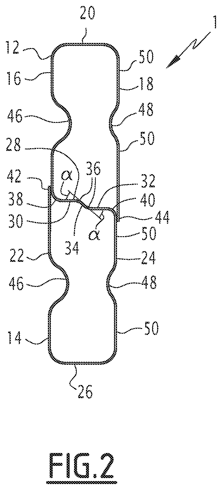
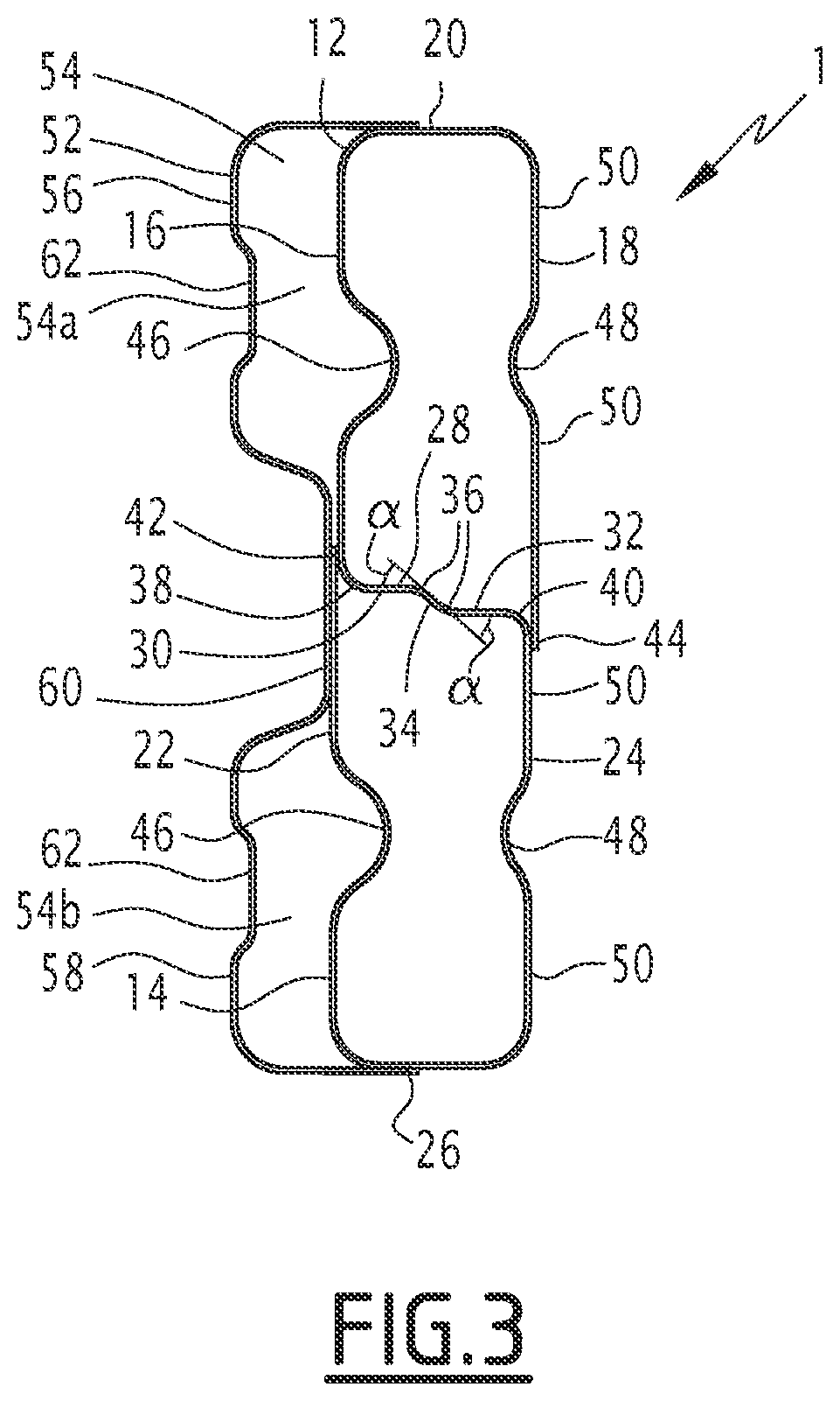
[0009]Having a central wall extending in at least two different planes, thereby creating a step in the central wall, allows improving the resistance of the bumper beam, which makes it able to resist a greater peak effort applied during the impact. Furthermore, the step creation makes it possible to reduce the length, measured in the direction in which the effort due to the impact is applied on the bumper beam, of the parts of the central wall extending in a single plane, which improves the absorption of energy during deformation of the bumper beam, therefore improving the minimum energy absorbed at a predetermined distance of deformation, and makes the bumper beam less likely to break during deformation. This result is obtained because the effort to induce buckling of a surface becomes lower as the length, in the longitudinal direction in which the effort is applied on the bumper beam during the impact, of a surface extending in a single plane increases. As compared to this situation wherein a central wall extends in a single plane, since having a change of plane in the central wall makes it possible to reduce the length of the surfaces extending in a single plane of the central wall in the longitudinal direction, buckling of these surfaces is delayed since the effort to induce buckling is greater. Delaying the buckling allows maintaining the hollow bodies of the upper beam and of the lower beam over a greater distance of deformation which improves the performances of the bumper beam during the impact in terms of absorbed energy.

Problems solved by technology

However, trying to improve one of these characteristics is generally detrimental to one and / or the other characteristics.

Method used


Image

  • Bumper beam having an 8 shaped cross-section
  • Bumper beam having an 8 shaped cross-section
  • Bumper beam having an 8 shaped cross-section

Examples


Embodiment Construction

[0036]In the description, the term “longitudinal” is defined according to the rear-front direction of a vehicle and the term “transversal” is defined according to the left-right direction of the vehicle. The terms “up”, “upper”, “lower” are defined relative to the elevation direction of a vehicle.

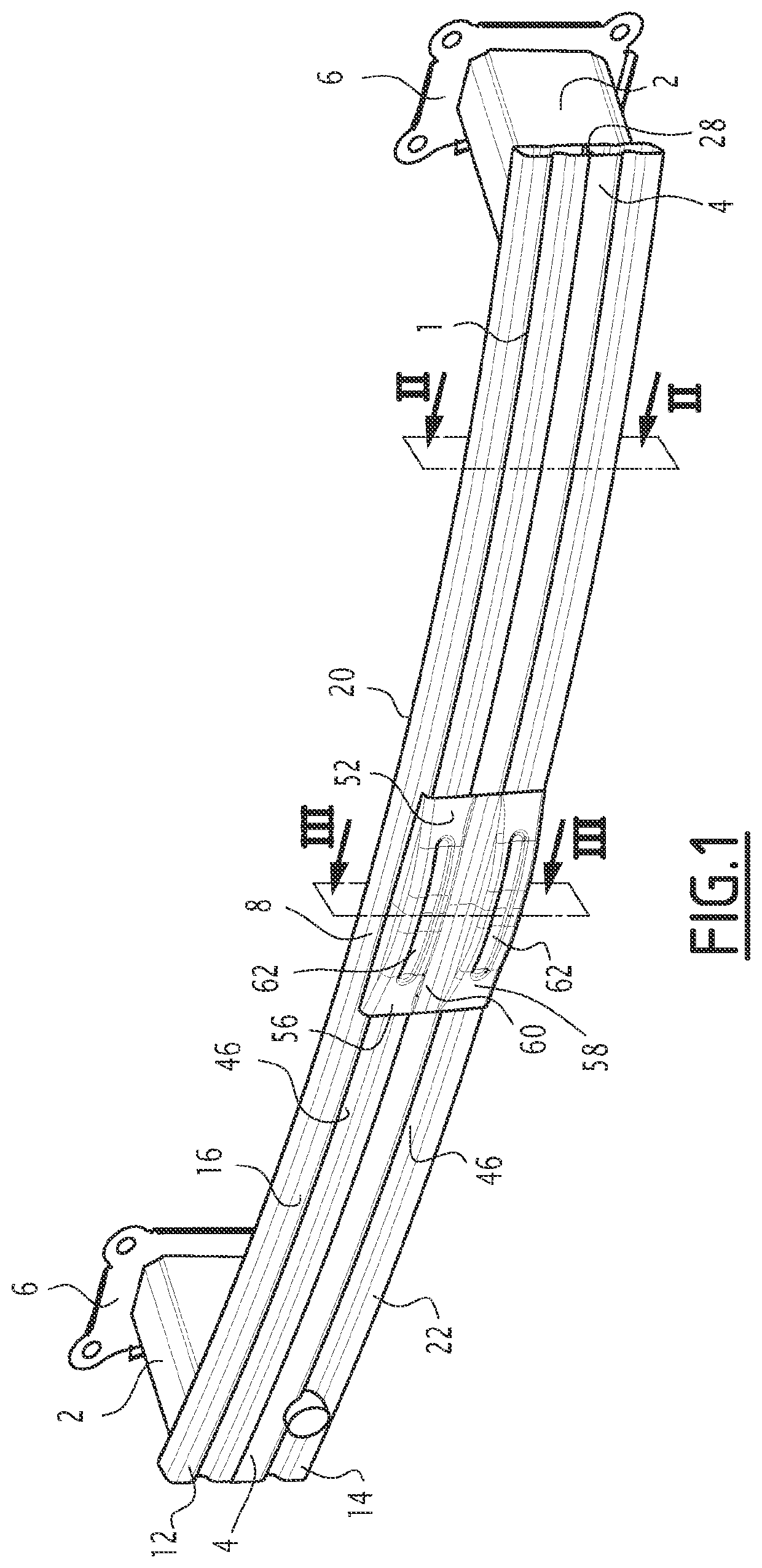
[0037]In reference to FIG. 1, a bumper beam assembly for an automotive vehicle is described. Such a bumper beam assembly is to be arranged at the front and / or at the rear of a vehicle to protect the motor compartment and the vehicle compartment in case of a front and / or rear impact against the vehicle.

[0038]The bumper beam assembly comprises a bumper beam 1 extending substantially transversally and two crash-boxes 2 extending in the longitudinal direction attached to the bumper beam 1 in the vicinity of each transversal ends 4 of the bumper beam 1. An attachment plate 6 is provided at the end of each crash-box 2 opposite the bumper beam 1 for attaching the bumper beam assembly to the body o...


PUM

PropertyMeasurementUnit
tensile strengthaaaaaaaaaa
thicknessaaaaaaaaaa
thicknessaaaaaaaaaa

Abstract

A bumper beam made of at least one roll formed steel sheet is described. The bumper beam contains an upper beam and a lower beam extending in a transversal direction, the upper beam and the lower beam each having a closed cross-section defined by a front wall, a rear wall, an upper wall and a lower wall, the upper wall and the lower wall joining the front wall to the rear wall, and a central wall extending between the front walls, the rear walls of the upper beam and of the lower beam forming both the lower wall of the upper beam and the upper wall of the lower beam, the central wall extending in at least two different planes.

Description

FIELD OF THE INVENTION[0001]The present invention provides a bumper beam for an automotive vehicle of the type made of at least one roll formed steel sheet comprising an upper beam and a lower beam extending in a transversal direction, said upper beam and said lower beam each having a closed cross-section defined by a front wall, a rear wall, an upper wall and a lower wall, the upper wall and the lower wall joining the front wall to the rear wall, wherein a central wall extends between the front walls and the rear walls of the upper beam and of the lower beam forms both the lower wall of the upper beam and the upper wall of the lower beam.[0002]The invention also provides a method for producing such a bumper beam.BACKGROUND OF THE INVENTION[0003]Bumper beams comprising an upper beam and a lower beam having a common central wall are known as “8-shaped” bumper beams. Such bumper beams are known for having good strength and impact characteristics, thanks to the central wall which incre...

Claims


Application Information

Patent Timeline
Patent Type & Authority Patents(United States)
IPC IPC(8): B60R19/18B21D5/08B21D53/88
CPCB60R19/18B21D5/086B21D53/88B60R2019/1826
Inventor HERISSON, DAMIENLAM, JIMMYHASENPOUTH, DANGIBEAU, ELIEVIAUX, IVAN
Owner ARCELORMITTAL INVESTIGACION Y DESARROLLO SL
Learn More