
Electronic device with multiple screens

a technology of electronic devices and screens, applied in the field of electronic devices, can solve the problems of limited image display functions, bulky and not easy to carry, and the size of the display body is limited to the size of the display body, so as to improve practicability, narrow the frame, and the effect of enlarging the display rang

Active Publication Date: 2021-03-02
COMPAL ELECTRONICS INC
View PDF18 Cites 5 Cited by
  • Summary
  • Abstract
  • Description
  • Claims
  • Application Information

AI Technical Summary

Benefits of technology

The patent is about an electronic device with multiple screens that can adjust the position of the expansion module according to needs. This can be done by sliding a keyboard, which can also drive the expansion module to lift and become the image extension of the second body, achieving the effect of narrowing the frame and enlarging the display range. The expansion module can also cover the outer frame of the second body to avoid segmentation during the display process. Furthermore, the expansion module can be separated from the first body and used independently, which makes it easier to use. Overall, this patent provides a better solution for enlarging the display range and solving image segmentation problem in electronic devices with multiple screens.

Problems solved by technology

Therefore, the image picture is limited to the size of the display body.
In addition, the functions of the existing display body are mostly limited to image display only.
However, the drawback of the external screen is that it is bulky and not easy to carry, and the external screen is typically disposed at the edges of both sides of the display body, which causes the shift of the center of gravity and the viewing angle of the notebook computer, and thus making it unergonomic.

Method used


Image

  • Electronic device with multiple screens
  • Electronic device with multiple screens
  • Electronic device with multiple screens

Examples


Embodiment Construction

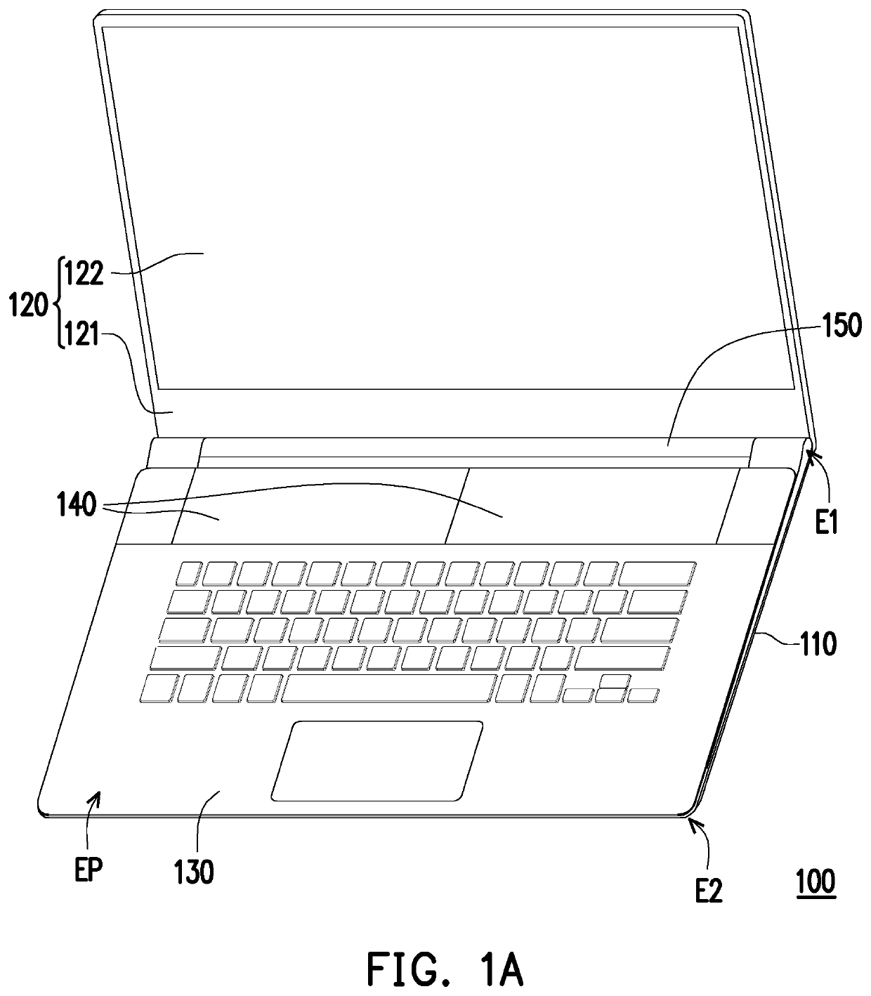
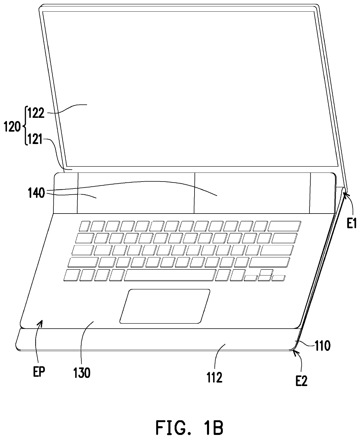
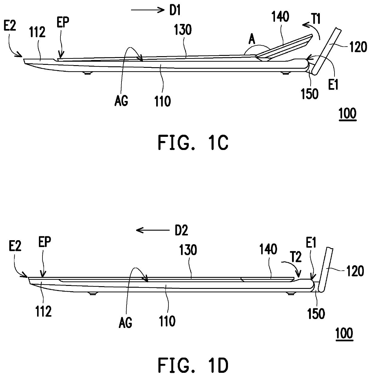
[0023]FIG. 1A is a schematic perspective view of an electronic device with multiple screens in a normal mode according to an embodiment of the disclosure. FIG. 1B is a schematic perspective view of the electronic device with multiple screens of FIG. 1A in a lifting mode. FIG. 1C is a schematic side view of the electronic device with multiple screens of FIG. 1B in the lifting mode. FIG. 1D is a schematic side view of the electronic device with multiple screens of FIG. 1A in the normal mode.

[0024]Please refer to FIG. 1A to FIG. 1D, the electronic device 100 with multiple screens of the disclosure includes a first body 110, a second body 120, a keyboard 130 and at least one expansion module 140. The first body 110 is, for example, a host and equipped with various electronic components. The first body 110 has a sliding rail assembly 111, a first end E1, and a second end E2. The sliding rail assembly 111 is fixed in the inner space of the first body 110. The second body 120 is, for examp...


PUM


Abstract

An electronic device with multiple screens includes a first body, a second body, a keyboard, and at least one expansion module. The first body has a sliding rail assembly, a first end and a second end. The second body is rotatably connected to the first end of the first body. The sliding base is slidably connected to the sliding rail assembly of the first body. The lifting base is pivotally connected to one side of the keyboard facing the first end and is slidably connected to the sliding rail assembly. The at least one expansion module is detachably connected to the lifting base and is disposed between the second body and the keyboard. When the keyboard slides toward the second body, the sliding base is driven to move along the sliding rail assembly and away from the second end of the first body.

Description

CROSS-REFERENCE TO RELATED APPLICATION[0001]This application claims the priority benefit of U.S. provisional application Ser. No. 62 / 836,743, filed on Apr. 22, 2019. The entirety of the above-mentioned patent application is hereby incorporated by reference herein and made a part of specification.BACKGROUNDField of the Disclosure[0002]The disclosure relates to an electronic device, and in particular to an electronic device with multiple screens and switchable use modes.Description of Related Art[0003]Conventional notebook computer is composed of a display body and a host. Therefore, the image picture is limited to the size of the display body. In addition, the functions of the existing display body are mostly limited to image display only. In light of the above, an external screen has been developed, which can be connected to one side of the display body to enlarge the display range of picture. However, the drawback of the external screen is that it is bulky and not easy to carry, an...

Claims


Application Information

Patent Timeline
Patent Type & Authority Patents(United States)
IPC IPC(8): G06F1/16
CPCG06F1/1649G06F1/165G06F1/1616G06F1/1654G06F1/1624G06F1/1632G06F1/1662G06F1/1647G06F1/1681G06F1/1675
Inventor LIU, YI-HSUNTSENG, HSIAO-WENYANG, YAO-HSIENTZOU, JYH-CHYANG
Owner COMPAL ELECTRONICS INC
Learn More