Efficiently measuring phase differences in an angle of arrival system

a technology of phase difference and angle of arrival, applied in direction finders using radio waves, multi-channel direction-finding systems using radio waves, instruments, etc., can solve the problems of reducing the overall accuracy of the angle of arrival measurement, implementing a full receiver for each antenna, and significantly increasing the complexity of the system. to achieve the effect of efficient measurement of phase differences

Active Publication Date: 2021-03-02
L3 TECH INC
View PDF14 Cites 2 Cited by
  • Summary
  • Abstract
  • Description
  • Claims
  • Application Information

AI Technical Summary

Benefits of technology

[0005]The present invention extends to an angle of arrival system that is configured to efficiently measure phase differences. The angle of arrival system includes a master receiver for demodulating the signal received at one antenna and for implementing a tracking loop to identify the timing of symbols within the signal. This timing information can be fed back as a synchronization signal to a despreader in the master receiver and to a despreader in each of a number of slave receivers to synchronize the timing at which each signal is despread. Because despreading is synchronized, the outputs of the despreaders can be used to directly calculate phase differences between each pair of signals. In this way, the slave receivers do not need to implement a demodulator or a tracking loop.
[0006]Because a single master receiver is employed, the overall complexity of the angle of arrival system is greatly reduced. Additionally, because phase difference is measured directly, as opposed to first determining the phases and calculating the differences between the determined phases, the phase differences are less susceptible to variations in the performance of the angle of arrival system.

Problems solved by technology

Various issues exist with such techniques.
In angle of arrival systems that employ many antennas, implementing a full receiver for each antenna significantly increases the system's complexity.
Also, tracking loops could slip and therefore, to implement a reliable system, a mechanism for detecting and correcting cycle slips is required which further increases the complexity of the system.
As a result, the tracking loop performs little averaging which reduces the overall accuracy of the angle of arrival measurements.

Method used


Image

  • Efficiently measuring phase differences in an angle of arrival system
  • Efficiently measuring phase differences in an angle of arrival system
  • Efficiently measuring phase differences in an angle of arrival system

Examples


Embodiment Construction

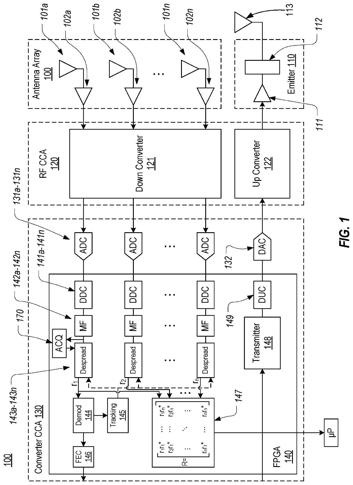
[0016]In this specification, the term “master receiver” or “full receiver” will be used to refer to a receiver that includes components for despreading and demodulating a signal. In contrast, the term “slave receiver” will be used to refer to a receiver that includes components for despreading a signal, but does not include (or does not employ) components for demodulating the signal. An angle of arrival system configured in accordance with embodiments of the present invention includes a master receiver and multiple slave receivers.

[0017]FIG. 1 generally illustrates the architecture of an angle of arrival system 100 that is configured in accordance with embodiments of the present invention. Angle of arrival system 100 includes the following general components: an antenna array 100, an emitter 110, a radio frequency (RF) circuit card assembly (CCA) 120, and a converter CCA 130. Each of these components is represented in dashed lines to indicate that the components may be incorporated ...


PUM


Abstract

An angle of arrival system is configured to efficiently measure phase differences. The angle of arrival system includes a master receiver for demodulating the signal received at one antenna and for implementing a tracking loop to identify the timing of symbols within the signal. This timing information can be fed back as a synchronization signal to a despreader in the master receiver and to a despreader in each of a number of slave receivers to synchronize the timing at which each signal is despread. Because despreading is synchronized, the outputs of the despreaders can be used to directly calculate phase differences between each pair of signals. In this way, the slave receivers do not need to implement a demodulator or a tracking loop. When the received signal is a non-spread signal, the phase differences between each pair of signals can be calculated directly from the modulated samples of each pair of signals without despreading.

Description

CROSS-REFERENCE TO RELATED APPLICATIONS[0001]N / ABACKGROUND[0002]Geolocation refers to techniques for determining the geographic location of an object. Various types of geolocation exist. The present invention is applicable to environments where the object to be geolocated emits a signal. In such environments, various measurements can be performed on the received signal to estimate the location of the emitting object. For example, a receiver can perform angle (or direction) of arrival techniques to estimate the angle between the emitting object and the boresight vector of the receiver's antennas.[0003]Angle of arrival techniques are often performed by detecting phase differences at a number of antennas that receive the signal emitted by the object. In such systems, each antenna is coupled to a receiver that is configured to detect the phase of the signal received at the corresponding antenna. To accomplish this phase detection, each receiver implements a tracking loop to produce an o...

Claims


Application Information

Patent Timeline
Patent Type & Authority Patents(United States)
IPC IPC(8): G01S5/04G01S3/48G01S3/04G01S3/46H01Q21/00H04L7/00G01S3/74G01S3/72
CPCG01S3/48G01S3/043G01S3/46G01S3/72G01S3/74H01Q21/00H04L7/0008
Inventor ZARUBICA, RADIVOJEKINGSTON, SAMUEL C.THOMSON, LARRY S.ADAMSON, SCOTT N.TWITCHELL, EDWIN R.BAGLEY, ZACHARY C.
Owner L3 TECH INC
Why Eureka
Try Eureka