Rotation-type manipulation device, control method for the same, and program

a technology of rotational control and control method, which is applied in the direction of mechanical control device, tactile signalling system, stopping arrangement, etc., can solve the problems of reducing the quality of manipulation feeling, difficult to obtain clear click feeling, and likely to occur torque like vibration change, etc., to achieve clear click feeling, resistive force, and easy to stably stop the rotation

Active Publication Date: 2021-02-09
ALPS ALPINE CO LTD
View PDF3 Cites 2 Cited by
  • Summary
  • Abstract
  • Description
  • Claims
  • Application Information

AI Technical Summary

Benefits of technology

[0007]With this rotational-type manipulation device, when the control torque in the encouragement direction is reduced as the rotational angle changes, a sense that the drawing force is weakened as the manipulation member rotates is obtained. Also, when the control torque in the suppression direction is increased as the rotational angle changes, a sense that a resistive force is increased as the manipulation member rotates is obtained. Since this change in the control torque occurs, it becomes easy to stably stop the rotation of the manipulation member in an area in which the control torque changes from the encouragement direction to the suppression direction. Also, a click feeling accompanying a rotation manipulation is produced due to a change of the control torque.
[0008]Furthermore, with this rotational-type manipulation device, when the rotational angle passes through the transition area in which the control torque changes from the encouragement direction to the suppression direction, the braking torque based on a friction force is increased in a pulse state. Therefore, when the rotational angle passes through the transition area, a clearer click feeling is produced without a change like vibration being caused in the control torque. In addition, since the stopping of the rotation in the transition area is assisted by the braking torque increased in a pulse state, it becomes easy to stop the rotation in the transition area and the manipulation feeling becomes more superior.

Problems solved by technology

Therefore, if torque is changed so steep, a change in torque like vibration is likely to occur.
If torque changes like vibration, it becomes difficult to obtain a clear click feeling.
This is problematic in that the quality of a manipulation feeling is lowered.

Method used


Image

  • Rotation-type manipulation device, control method for the same, and program
  • Rotation-type manipulation device, control method for the same, and program
  • Rotation-type manipulation device, control method for the same, and program

Examples


Embodiment Construction

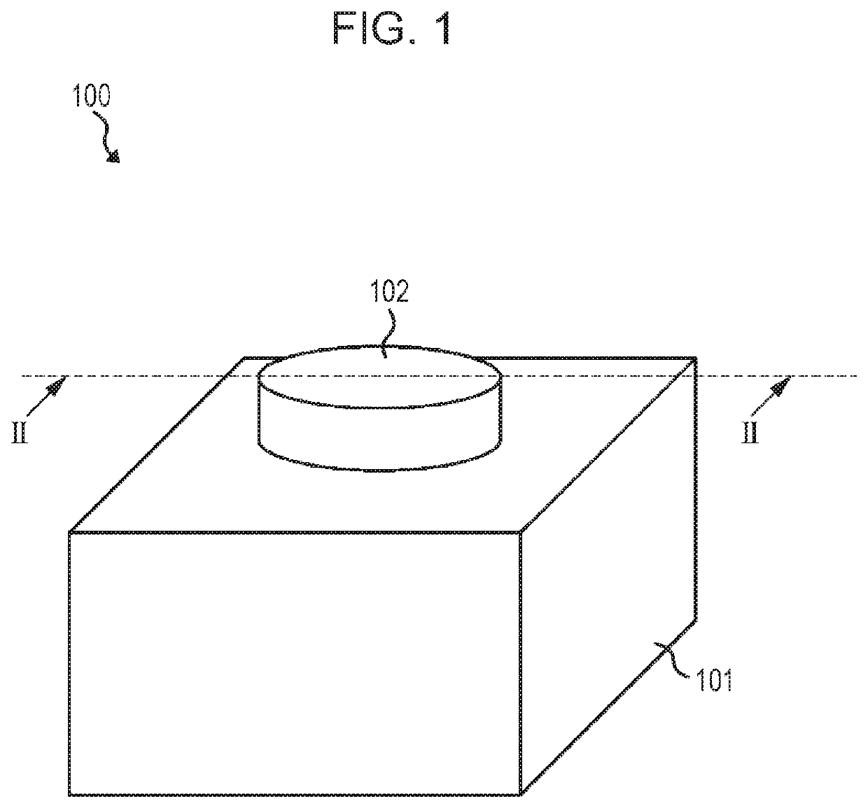
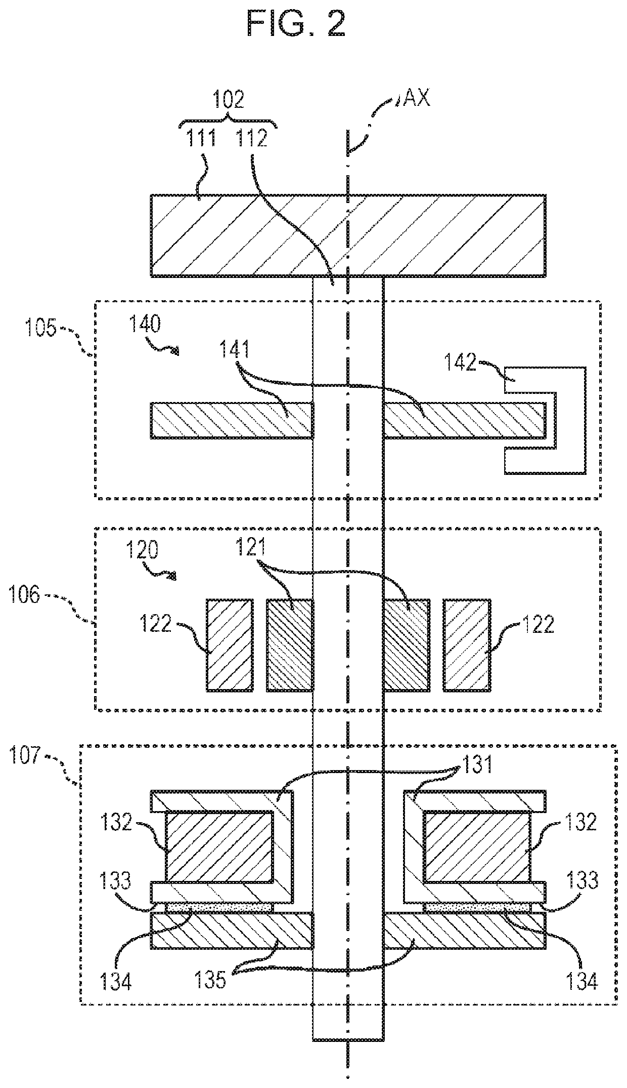
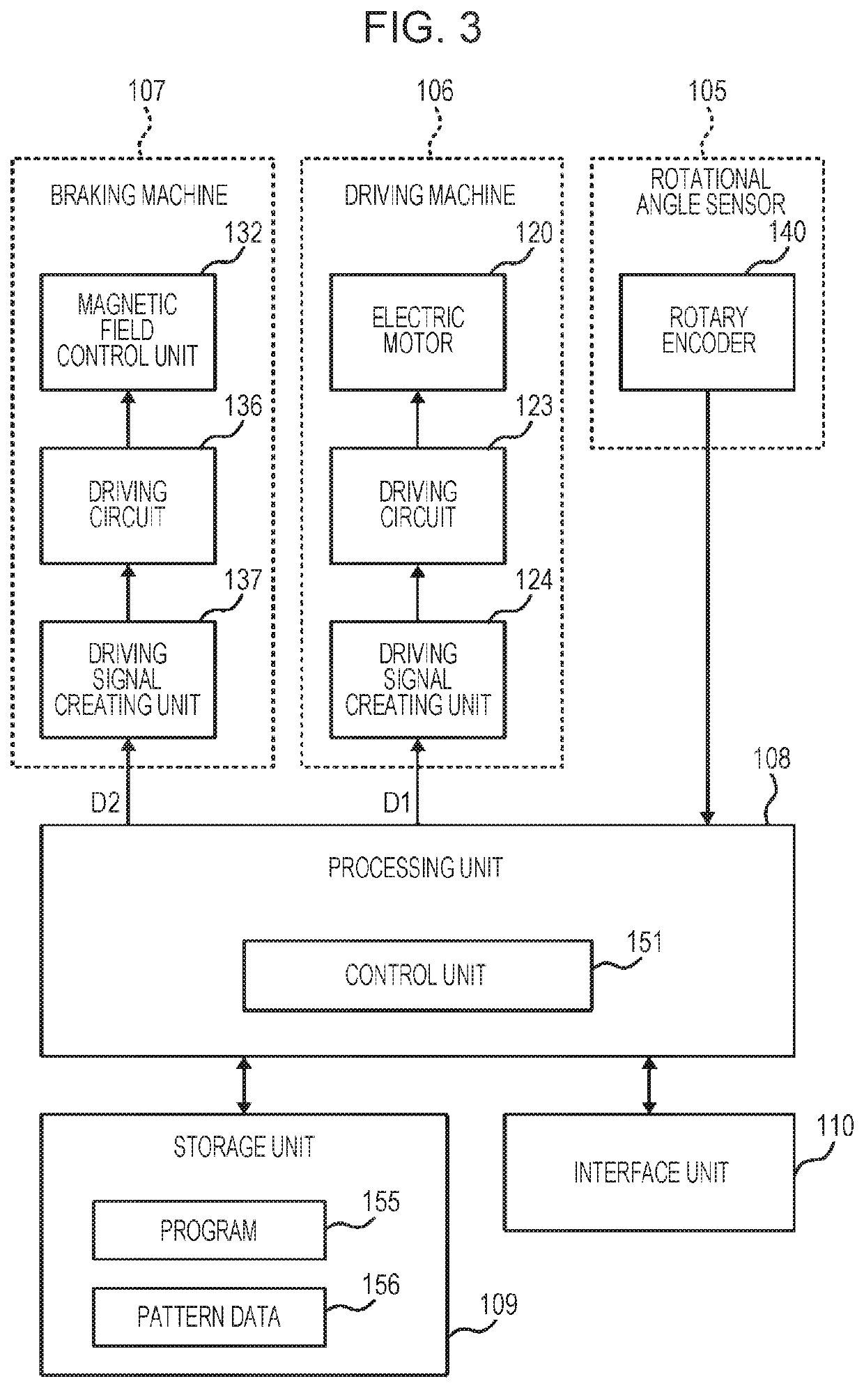
[0019]A rotation-type manipulation device according to an embodiment of the present invention will be described below with reference to the drawings. FIG. 1 is a perspective view illustrating an example of the appearance of the rotation-type manipulation device 100 according to this embodiment. FIG. 2 is a partial cross-sectional view of the rotation-type manipulation device 100 as taken along line II-II in FIG. 1. FIG. 3 is a block diagram illustrating an example of the structure of the rotation-type manipulation device 100 illustrated in FIG. 1.

[0020]As illustrated in FIG. 1, the rotation-type manipulation device 100 has a manipulation member 102 that can be rotated through a rotation manipulation by the manipulator, and also has a case 101 that rotatably supports the manipulation member 102. The rotation-type manipulation device 100 creates manipulation information related to rotation manipulations such as, for example, the rotational angle, rotational position, and rotational sp...


PUM


Abstract

Braking torque based on a friction force is increased in a pulse state in a transition area in which control torque changes from a direction to encourage the rotation of a manipulation member to a direction to suppress the rotation. This braking torque based on a friction force does not cause vibration unlike the driving torque of an electric motor even if the braking torque is steeply increased. Therefore, when the rotational angle passes through the transition area, a clearer click feeling can be generated without a change like vibration being caused in control torque. When the manipulation member is rotated fast, the braking torque in a pulse state is likely to be felt as vibration.

Description

CLAIM OF PRIORITY[0001]This application is a Continuation of International Application No. PCT / JP2018 / 015508 filed on Apr. 13, 2018, which claims benefit of priority to Japanese Patent Application No. 2017-084370 filed on Apr. 21, 2017. The entire contents of each application noted above are hereby incorporated by reference.BACKGROUND1. Field of the Disclosure[0002]The present disclosure relates to a rotation-type manipulation device that can control a manipulation feeling accompanying a rotation manipulation and to a control method for the rotation-type manipulation device and a program.2. Description of the Related Art[0003]A known rotation-type manipulation device accepts an input for the switching of the transmission of a vehicle, volume adjustment for an audio device, or the like through the rotation of a manipulation member. A force sense imparting input device described in Japanese Unexamined Patent Application Publication No. 2004-114201, for example, has a manipulation memb...

Claims


Application Information

Patent Timeline
Patent Type & Authority Patents(United States)
IPC IPC(8): G08B6/00F16D57/00G05G1/08G05G5/03H02P6/08H02P6/24
CPCG08B6/00F16D57/002G05G1/08G05G5/03H02P6/08H02P6/24G05G2505/00G05G5/06
Inventor WAKUDA, HIROSHI
Owner ALPS ALPINE CO LTD
Why Eureka
Try Eureka