
Active smoke filtration for insufflation

a technology of active smoke and insufflation, which is applied in the field of active smoke filtration units, can solve the problems of reducing the likelihood of pressure loss, noisy, and less effective than desired, and reducing the volume of water used to adequately humidify the gases, so as to improve the vision of the surgeon, remove smoke, and maintain the pressure within the body cavity

Active Publication Date: 2021-02-09
FISHER & PAYKEL HEALTHCARE LTD
View PDF31 Cites 0 Cited by
  • Summary
  • Abstract
  • Description
  • Claims
  • Application Information

AI Technical Summary

Benefits of technology

The patent describes an improved system for removing smoke during surgeries. The system uses a compressor to create a recirculating flow of insufflation gases, which helps to maintain pressure within the body and reduces the likelihood of pressure loss during the filtration process. The system also includes a humidifier which helps to reduce the volume of water used to humidify the gases and can help to mitigate desiccation and complications related to temperature. The technical effects of this system include better visibility for the surgeon, reduced energy consumption, and improved patient outcomes.

Problems solved by technology

While filtration apparatus and techniques have been used in the past, those apparatus and techniques have proven to be inefficient, noisy, and less effective than desired.
Recirculation of insufflation gases reduces the likelihood of pressure loss during the filtration process.
Also, when the circuit includes a humidifier, moisture can be maintained within the system, thereby reducing the volume of water used to adequately humidify the gases.
Recirculating insufflation gases outside of the body of the patient, however, can pose certain challenges, especially when the insufflation gases are conditioned.
For example, recirculating gases outside of the body can result in cooling of the gases, which is counter to the goal of heating and humidifying the gases.
Entrainment of room air into the recirculation circuit can also result in cooling and drying of the insufflation gases.
Moreover, cooling of heated and humidified gases can result in condensation, and condensation can inhibit effective recirculation and / or cloud the vision of the surgeon inside the body cavity.

Method used


Image

  • Active smoke filtration for insufflation
  • Active smoke filtration for insufflation
  • Active smoke filtration for insufflation

Examples


Embodiment Construction

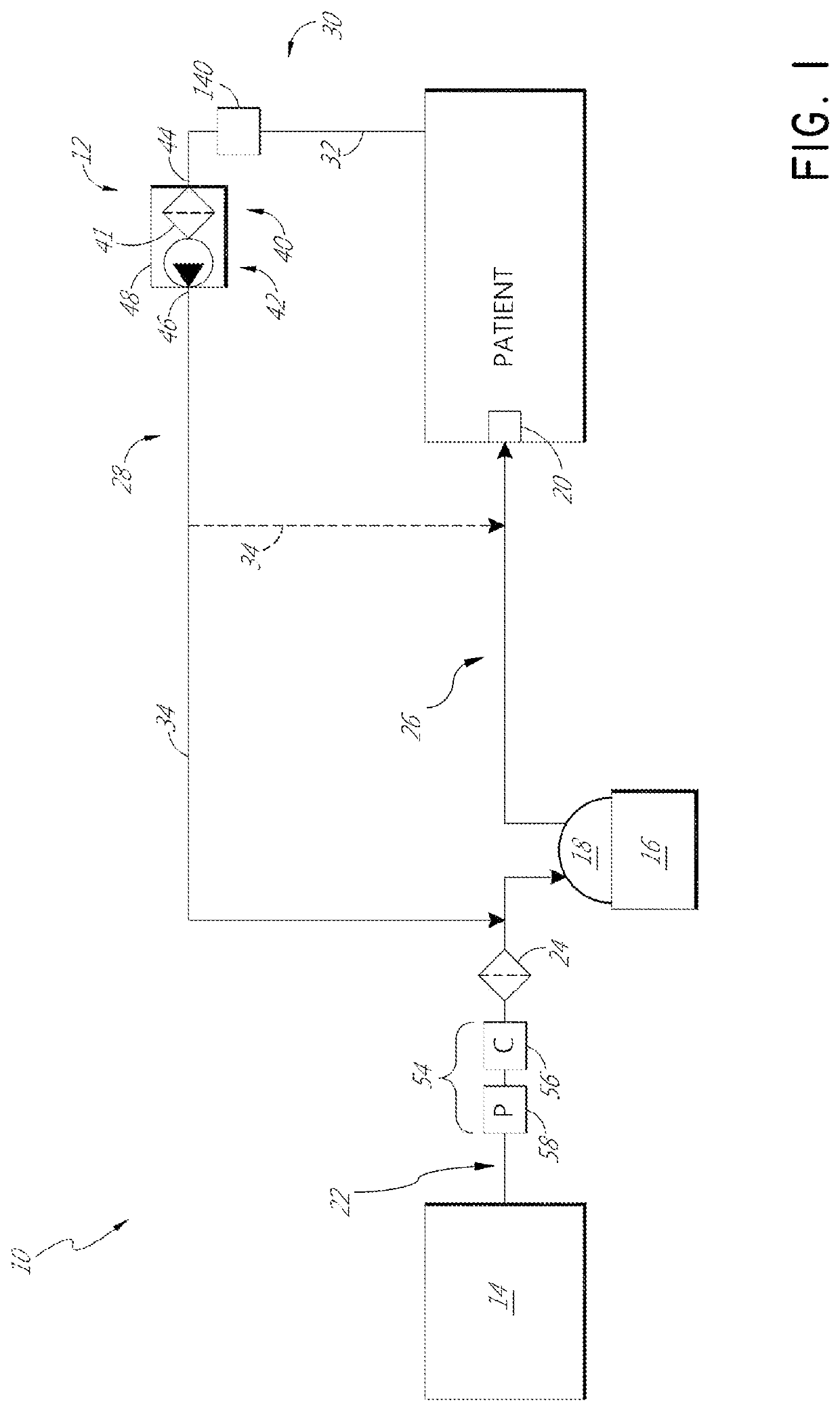
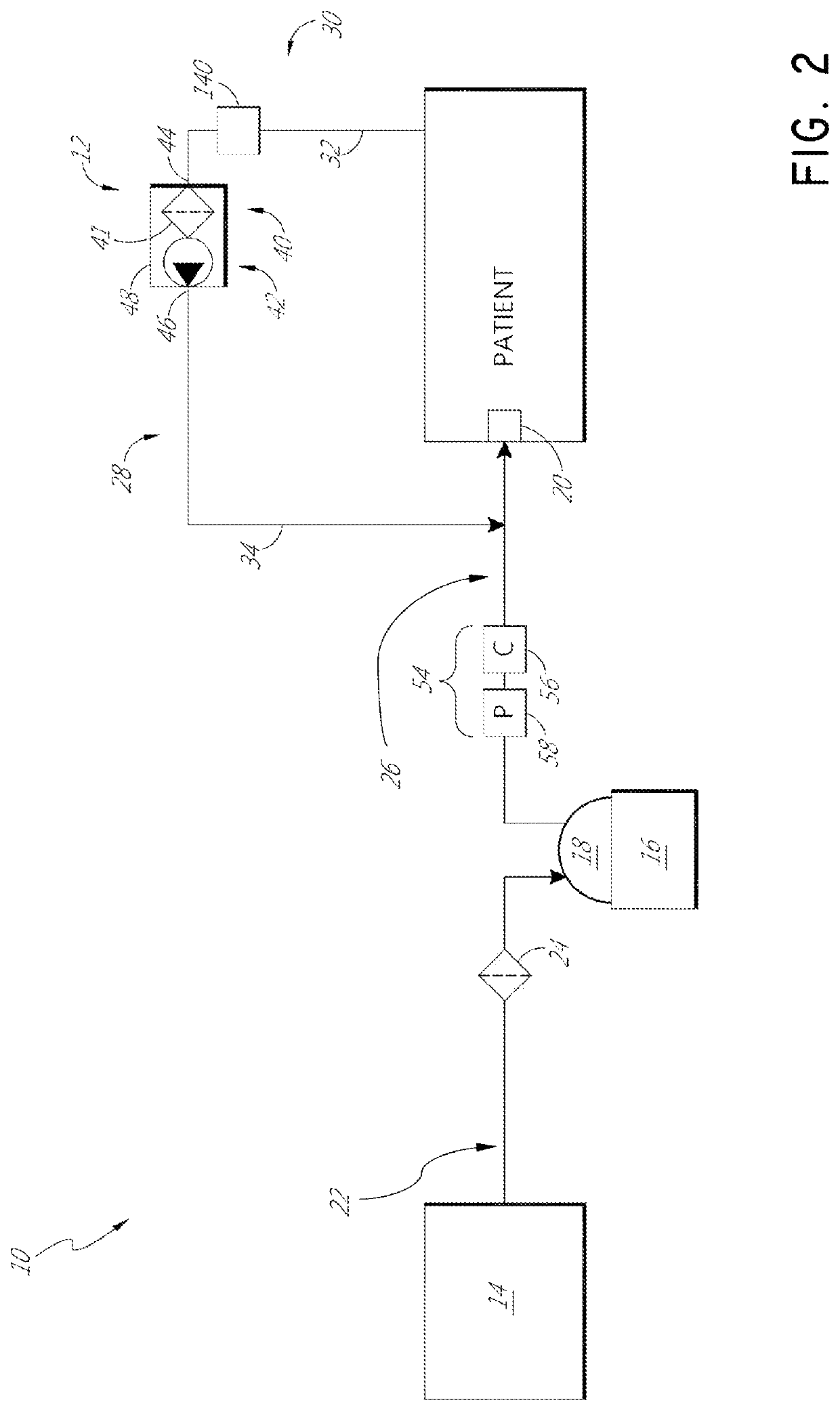
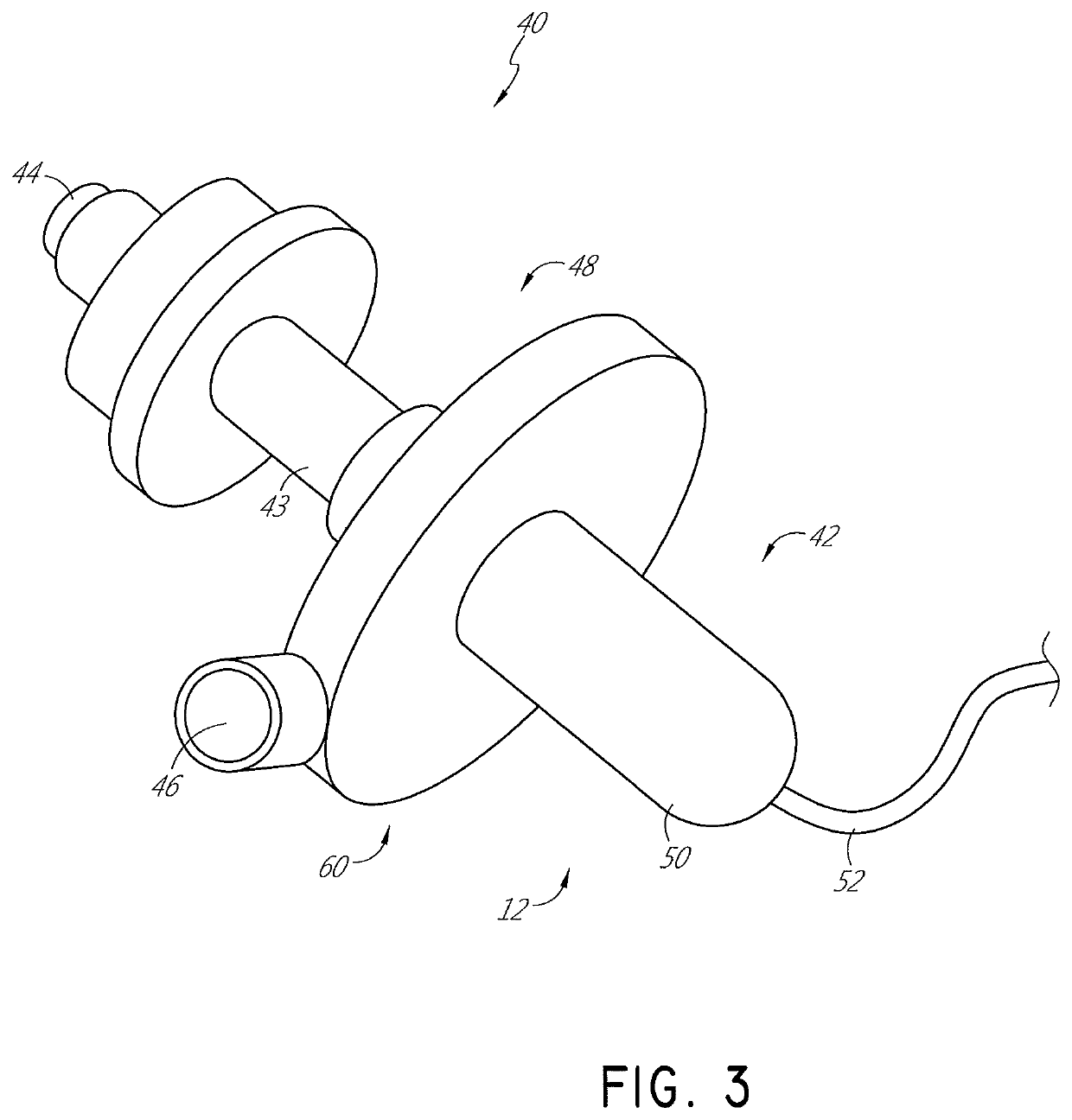
[0033]With reference now to FIG. 1, an example insufflation system 10 that comprises an active filtration unit 12 is illustrated schematically. In some configurations, the active filtration unit 12 is specifically configured to be disposable (i.e., a consumable product). In other configurations, the active filtration unit 12 can be integrated into other components and / or be sterilizable.

[0034]The illustrated insufflation system 10 comprises a primary flow generator 14. The primary flow generator 14 can be designed and configured to control at least one of the pressure and the flow rate of gases that will be supplied to the patient during use. The primary flow generator 14 can have any suitable configuration. In some configurations, the primary flow generator 14 can comprise a compressed gases cylinder and a regulator valve assembly. In some configurations, the primary flow generator 14 can comprise a pump that supplies insufflation gases. The primary flow generator 14 can provide a ...


PUM


Abstract

An active smoke filtration unit is used to remove smoke during laparoscopic surgery. The active smoke filtration unit is part of a recirculation circuit. The recirculation circuit is pneumatically isolated from a primary flow generator, such as an insufflator, by a valve assembly. The active smoke filtration unit can be housed separately from the valve assembly or together with the valve assembly. The recirculation circuit can include a humidifier to heat and humidify the insufflation gases.

Description

INCORPORATION BY REFERENCE TO ANY PRIORITY APPLICATIONS[0001]Any and all applications for which a foreign or domestic priority claim is identified in the Application Data Sheet as filed with the present application are hereby incorporated by reference under 37 CFR 1.57.BACKGROUND[0002]Technical Field[0003]The present disclosure generally relates to active smoke filtration units for use during laparoscopic surgery, More particularly, the present disclosure relates to an active smoke filtration unit that is part of a generally closed recirculation circuit within a laparoscopic surgery insufflation system.[0004]Description of the Related Art[0005]In some systems used for laparoscopic surgery, the gases delivered to the patient are conditioned prior to delivery to the patient. In some such systems, the gases are heated and humidified prior to delivery to the patient, For example, a humidification system can be placed between an insufflator and a surgical cannula, As gases travel towards...

Claims


Application Information

Patent Timeline
Patent Type & Authority Patents(United States)
IPC IPC(8): A61M13/00A61B1/313A61M16/10A61M16/16A61B1/015A61M39/24
CPCA61M13/006A61M13/00A61B1/015A61B1/3132A61M16/107A61M16/109A61M16/1055A61M16/16A61M39/24A61M2205/3344A61M2205/75
Inventor SURENDRA, WISNU ARYAGHALIB, ALI GHALIB ABDUL RAHMANDOR-ZIDON, SHAHARSTREVENS, JOSEPH PATRICK WALTERBLACKHURST, MICHAEL JOSEPH
Owner FISHER & PAYKEL HEALTHCARE LTD
Learn More